Beam-end loaded plane frame joint pseudo-static test loading device

A loading device and quasi-static technology, applied in the seismic field of building structures, can solve problems such as instrument damage and test deviation, and achieve the effects of high experimental accuracy, easy control, and simple structure of the loading device

Inactive Publication Date: 2014-06-25
HOHAI UNIV
View PDF5 Cites 5 Cited by
  • Summary
  • Abstract
  • Description
  • Claims
  • Application Information

AI Technical Summary

Problems solved by technology

[0005] However, there is no rotating device at the loading end, and the beam will turn when loading. At this time, if the actuator cannot rotate with the beam, it will cause deviation in the test, and even cause damage to the instrument.

Method used


Image

  • Beam-end loaded plane frame joint pseudo-static test loading device
  • Beam-end loaded plane frame joint pseudo-static test loading device
  • Beam-end loaded plane frame joint pseudo-static test loading device

Examples


Embodiment Construction

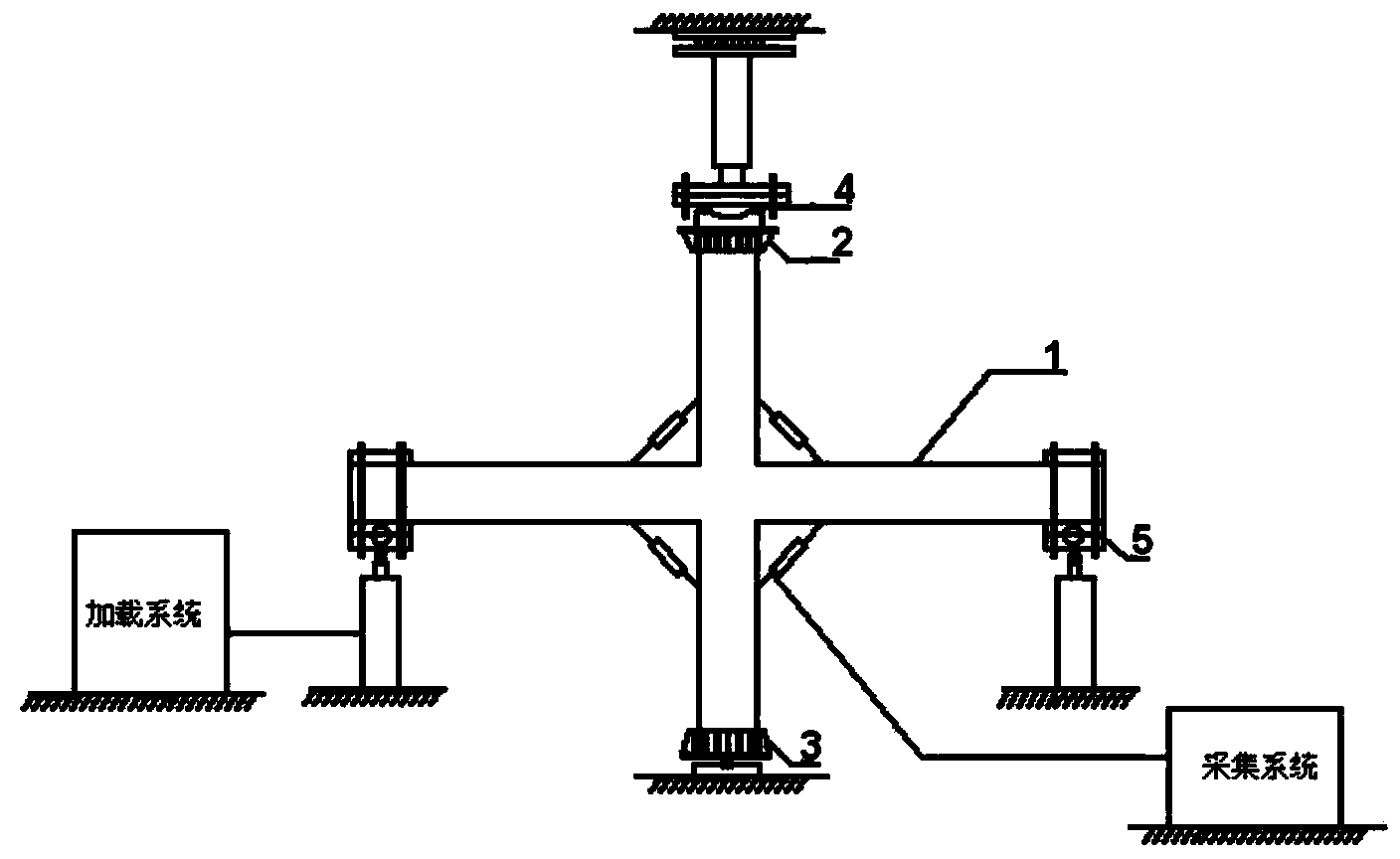
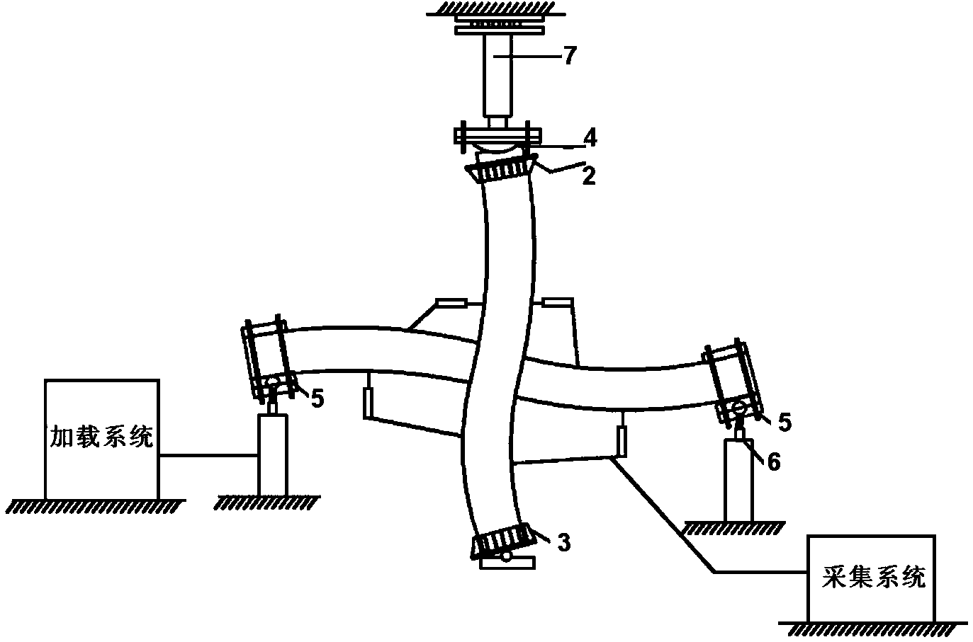
[0017] combine figure 1 and figure 2 The invention is described. The loading device for the pseudo-static test of the plane frame node loaded at the beam end of the present invention mainly includes a hinge column shoe 3, a column cap 2, a loading spherical hinge 5, a loading system and a data acquisition system. Hinge column shoe 3 is used to cover the column foot of component 1, and column cap 2 is used to cover the column head of component. Two sets of loading spherical hinges 5 are respectively installed on the left beam end and right beam end of the component. The loading system is connected with the loading spherical hinge, so that The components are loaded, and the data acquisition system is used to collect relevant mechanical information of the test components.

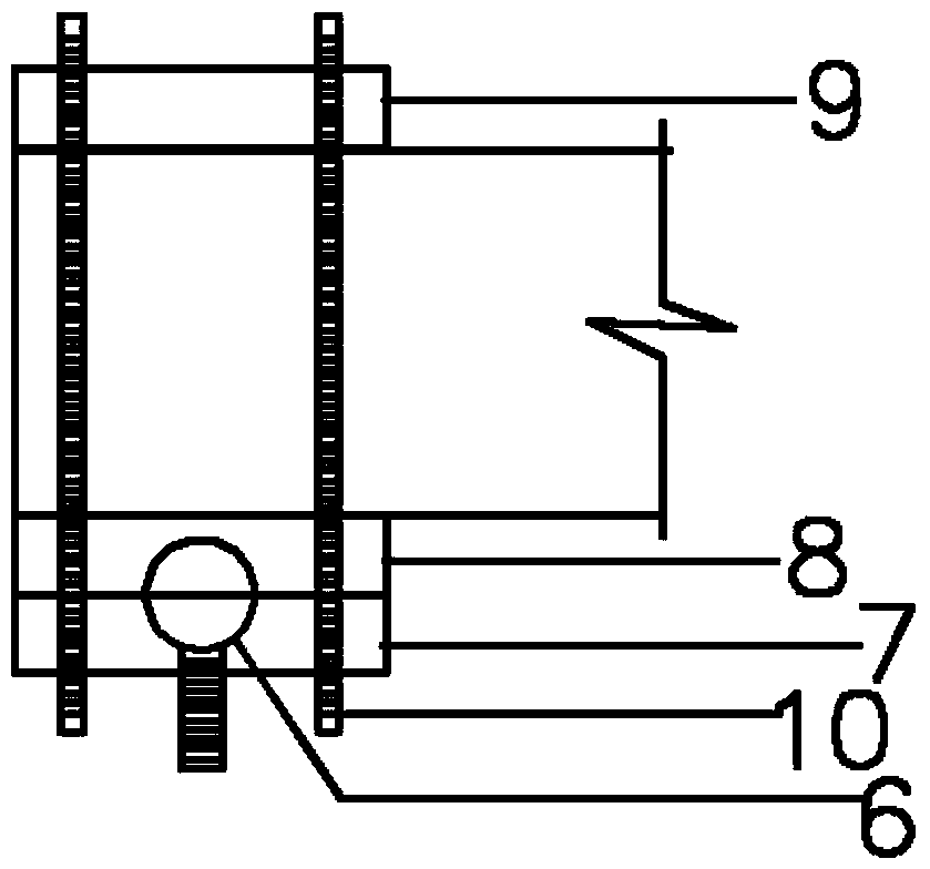
[0018] Such as image 3 and Figure 4 As shown, the loaded ball joint includes a ball core 6, a bottom plate 7, a lower top plate 8, an upper top plate 9, and a screw 10; the bottom plate is provided with...


PUM


Abstract

The invention discloses a beam-end loaded plane frame joint pseudo-static test loading device which comprises a hinge pillar boot which is used for being arranged on a component pillar foot in a sleeved mode, a pillar cap arranged on a component pillar head in a sleeved mode, two sets of loading ball hinges installed at the left beam end and the right beam end of a component respectively, a loading system connected with the loading ball hinges and a data collecting system. When the beam-end loaded plane frame joint pseudo-static test loading device works, the loading ball hinges rotate along with the test component, loading force is kept vertical all the time, the test accuracy is higher, and an instrument is not prone to damage. The beam-end loaded plane frame joint pseudo-static test loading device further has the advantages of being simple in structure, not eccentric in axial force, convenient to control and capable of providing four hinge support boundaries.

Description

technical field [0001] The invention belongs to the anti-seismic field of building structures, in particular to a loading device for a pseudo-static test of a plane frame node loaded at a beam end. Background technique [0002] At this stage, there are two test methods for low-cycle repeated loading of nodes: [0003] One kind of test method without lateral movement: this test method needs to process the structural loading outer frame, which is a geometrically variable system, and is used as hinge restraint for the test members. The equipment requirements are complicated, and it is difficult for general laboratories to provide them. This scheme is horizontally loaded, resulting in a large horizontal displacement. The horizontal sliding range reserved for the jack at the top of the column by installing the pulley is limited, which will still cause the eccentricity of the axial pressure on the top of the column, resulting in experimental errors. In addition, the test is loade...

Claims


Application Information

Patent Timeline
Patent Type & Authority Applications(China)
IPC IPC(8): G01M99/00
Inventor 韦芳芳瞿丽华廖学坤沈会张欢孙昆
Owner HOHAI UNIV
Why Eureka
Try Eureka