
Heat-insulation heat-discharge member and image formation device

A technology of images and components, which is applied in the field of heat insulation and heat removal components, can solve the problems of loud fan noise, increased machine energy consumption, and increased machine use costs, and achieve the effects of reducing costs, reducing energy consumption, and eliminating noise

Inactive Publication Date: 2014-06-25
RICOH KK
View PDF9 Cites 2 Cited by
  • Summary
  • Abstract
  • Description
  • Claims
  • Application Information

AI Technical Summary

Problems solved by technology

[0006] However, using a fan for forced exhaust not only complicates the structure of the image forming apparatus, but also causes temperature unevenness in the direction of the heat outflow path, so that for the fixing unit, there is a temperature difference in the long-axis direction. This makes the fixability of the toner different, and leads to a decrease in the quality of the image after fixing, resulting in a bad image
[0007] In addition, when the fan works continuously to discharge hot and humid air from the image forming device, the exhaust operation of the fan makes a lot of noise, and also greatly increases the energy consumption of the machine, and further increases the use cost of the machine

Method used


Image

  • Heat-insulation heat-discharge member and image formation device
  • Heat-insulation heat-discharge member and image formation device
  • Heat-insulation heat-discharge member and image formation device

Examples


Embodiment Construction

[0039] Hereinafter, the structural diagrams of the heat insulating and heat exhausting member and the image forming apparatus according to the present invention will be described in detail with reference to the accompanying drawings.

[0040]

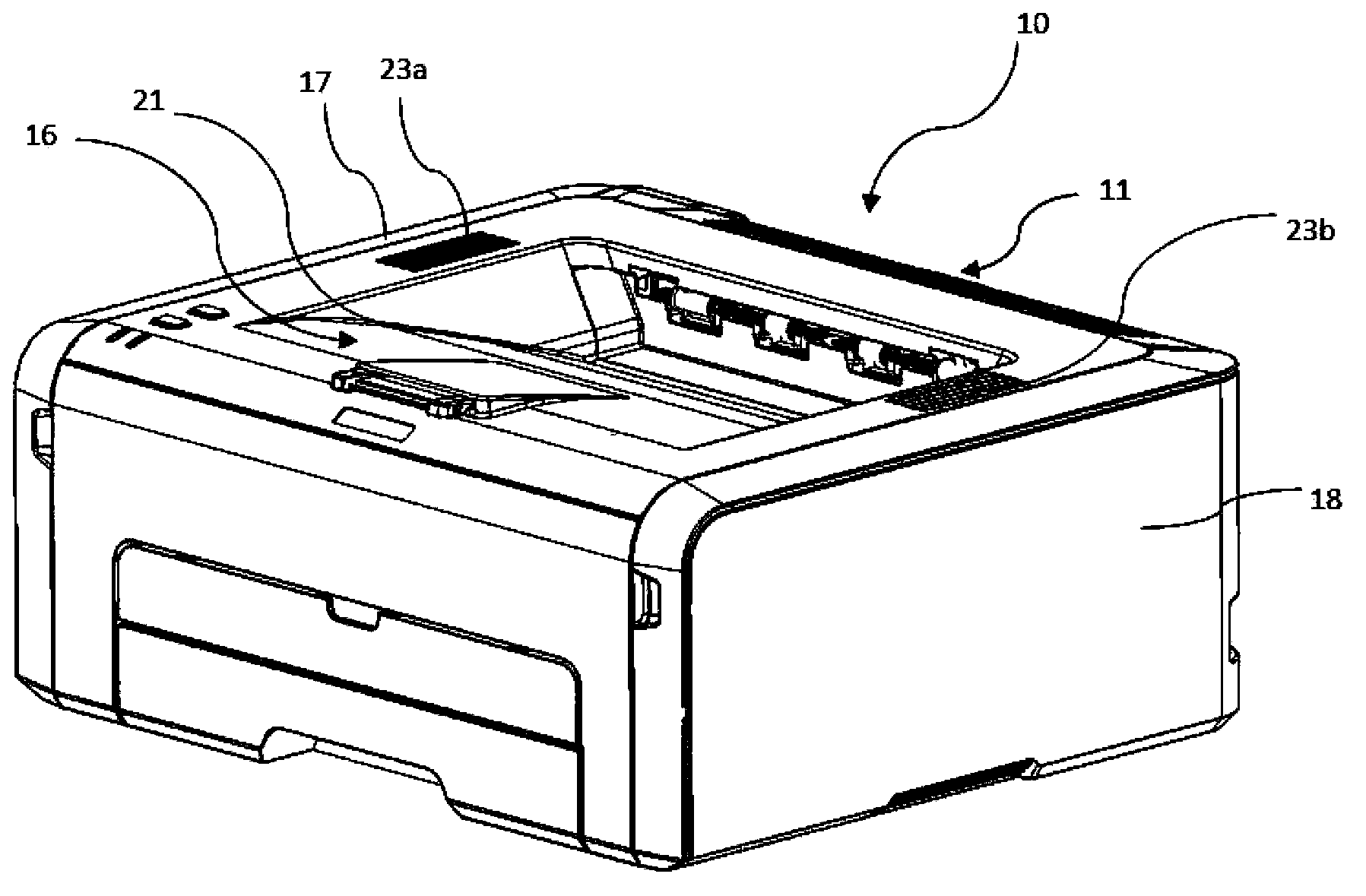
[0041] figure 1 is a perspective view of an embodiment of the image forming apparatus according to the present invention.

[0042] The image forming device 10 is connected to a host device not shown in the figure, and the image forming device 10 receives an electrical signal of image data sent from the host device.

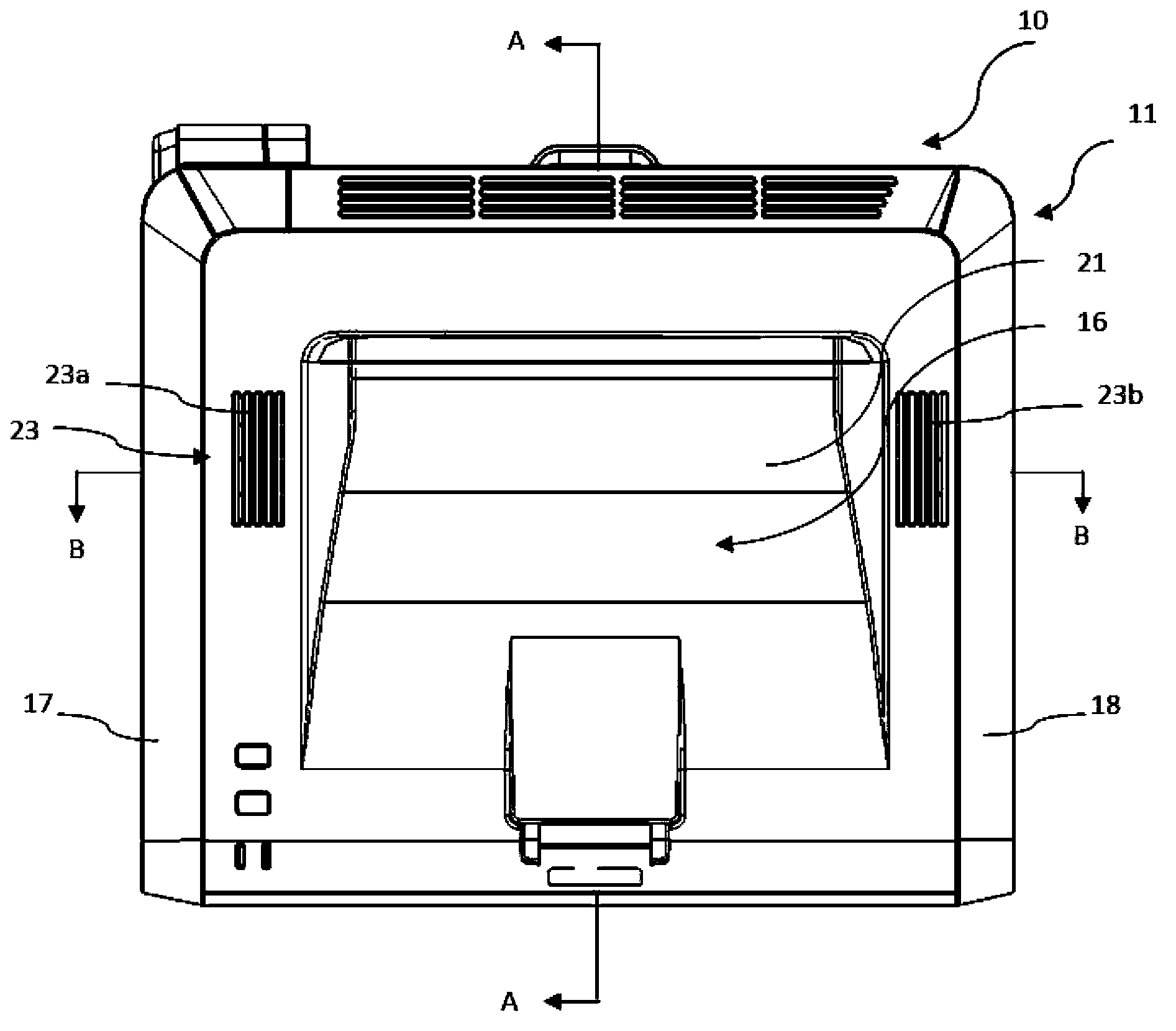
[0043] figure 2 is a plan view of an embodiment of the image forming apparatus according to the present invention.

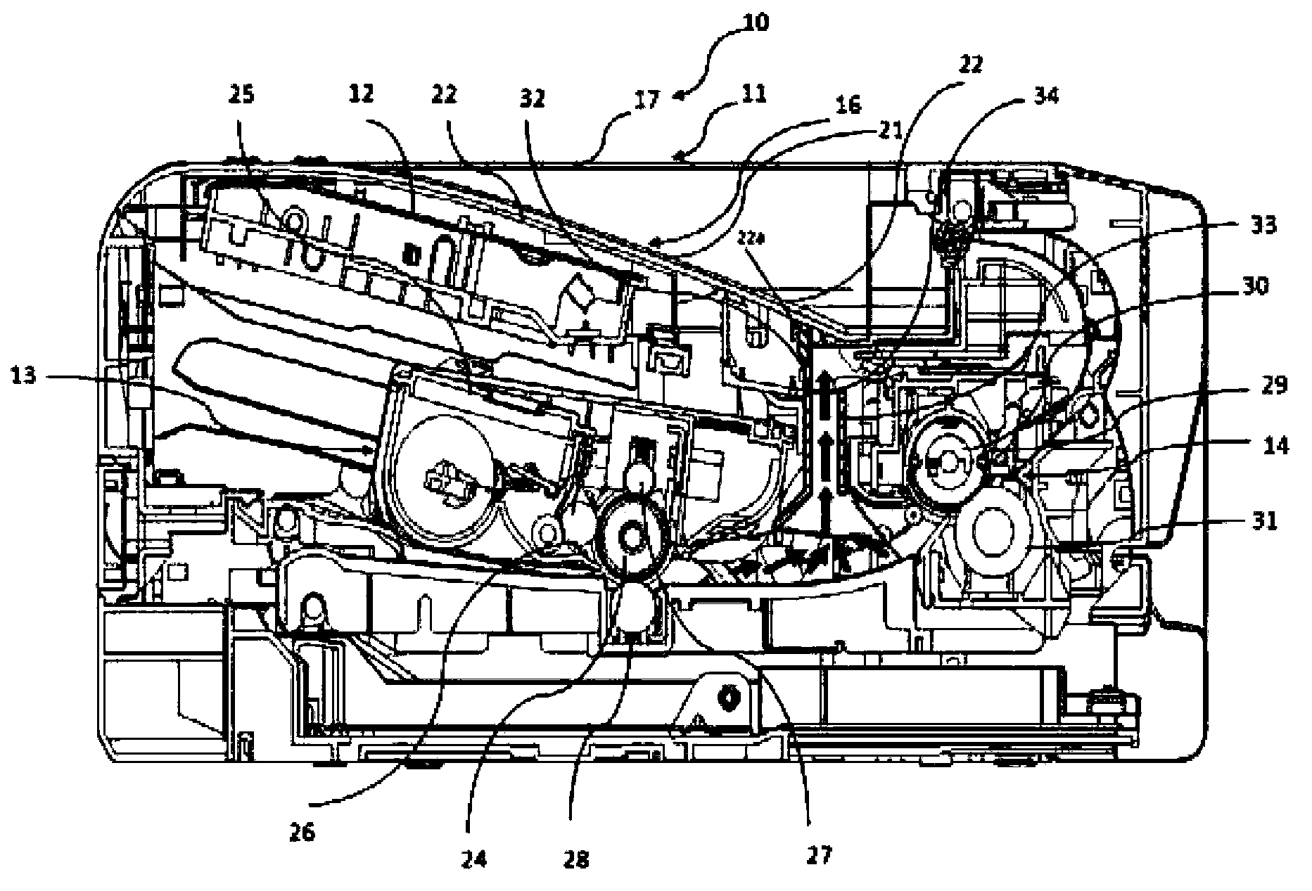
[0044] image 3 is true figure 2 A cross-sectional view taken along the A-A direction.

[0045] like figure 1 , 2 As shown in , 3 , the image forming apparatus 10 has a housing 11 , an exposure unit 12 , an image processing unit 13 , a fixing unit 14 , and a heat insulating and heat releasing membe...


PUM


Abstract

The invention provides a heat-insulation heat-discharge member which prevents heat from a fixing unit from flowing to an exposure unit without using a fan and naturally discharges the heat to the outside, and an image formation device with the heat-insulation heat-discharge member. The heat-insulation heat-discharge member of the invention is disposed between an exposure unit and a fixing unit of an image formation device, is used for at least stopping the heat from the fixing unit from flowing to the exposure unit and discharging the heat to the outside through two oppositely disposed gas vents on a frame of the image formation device, and is characterized in that the member comprises two end parts respectively communicated with the two gas vents, and at least two heat discharging paths which enable the heat to flow to the two gas vents respectively in opposite directions.

Description

technical field [0001] The present invention relates to a heat insulating and heat discharging member and an image forming apparatus including the heat insulating and heat discharging member. Background technique [0002] Generally, image forming devices such as laser printers and copiers contain: an exposure unit, an image processing unit, a fixing unit, and an upper cover. The exposure unit is used to provide light signals for forming a toner image. The lower part receives light signals from the exposure unit and forms a toner image, the fixing unit heats and fixes the toner image to complete image formation, and the upper cover is located above the exposure unit and the fixing unit for accumulating the image-formed print media. [0003] In the above-mentioned image forming device, the exposure unit and the image processing unit are usually placed on the same side, and the fixing unit is arranged on the other side. On the one hand, the exposure unit and the image processin...

Claims


Application Information

Patent Timeline
Patent Type & Authority Applications(China)
IPC IPC(8): G03G21/20G03G15/00
Inventor 姜乔马挺
Owner RICOH KK
Learn More