
Control method and electronic devices

A technology of electronic equipment and control method, applied in the field of control, to achieve the effect of improving accuracy and practicability

Active Publication Date: 2014-06-25
LENOVO (BEIJING) CO LTD
View PDF6 Cites 0 Cited by
  • Summary
  • Abstract
  • Description
  • Claims
  • Application Information

AI Technical Summary

Problems solved by technology

[0004] The technical problem to be solved by the present invention is to provide a control method and electronic equipment to solve the limitations of the existing single control method

Method used


Image

  • Control method and electronic devices
  • Control method and electronic devices
  • Control method and electronic devices

Examples


Embodiment 1

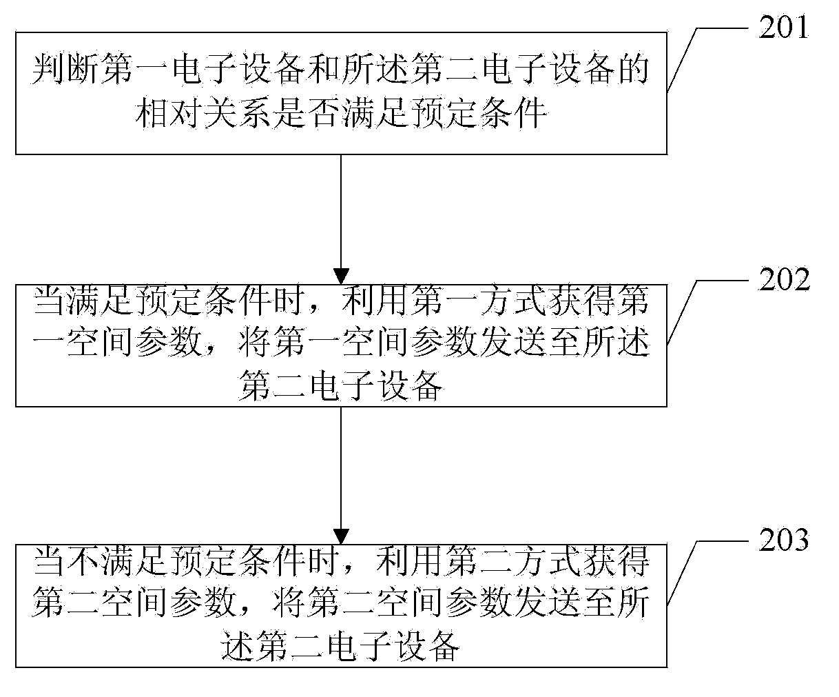
[0027] Embodiment 1 of the control method of the present invention is applied to a first electronic device, and the first electronic device is connected to a second electronic device for data. The first electronic device may specifically be an air mouse or a remote control, or may also be integrated with an operating keyboard, etc. The second electronic device may be a tablet computer, a television, a computer or other electronic devices, and this application does not limit its specific implementation form.

[0028] The first electronic device includes a first spatial parameter acquisition unit and a second spatial parameter acquisition unit, and the second electronic device includes a display unit and a transmitting unit that has a predetermined relative positional relationship with the display unit (for example, the transmitting unit is in the center of the upper edge of the panel of the display unit).

[0029] Such as figure 2 As shown, embodiment 1 of the control method ...

Embodiment 2

[0046] Embodiment 2 of the control method of the present invention is applied to the first electronic device, and the first electronic device is connected to the second electronic device for data. The first electronic device can specifically be an air mouse or a remote control, or can also integrate an operating keyboard, etc. The second electronic device may be a tablet computer, a television, a computer or other electronic devices, and this application does not limit its specific implementation form.

[0047] The first electronic device includes a condition determination unit, a first spatial parameter acquisition unit, and a second spatial parameter acquisition unit, the first spatial parameter acquisition unit includes an image generation unit and a spatial parameter acquisition module, and the second electronic device includes The display unit and the emitting unit have a predetermined relative positional relationship with the display unit (for example, the emitting unit i...


PUM


Abstract

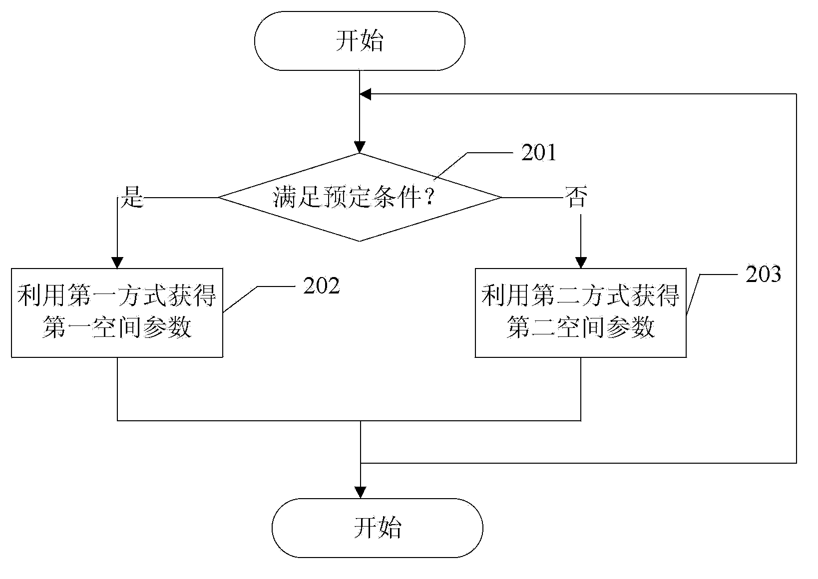
The invention relates to a control method and electronic devices. The control method is applied to a first electronic device which is in data connection with a second electronic device. The control method includes: judging whether correlation of the first and second electronic devices meets preset conditions or not; if yes, acquiring a first spatial parameter by a first method, and transmitting the first spatial parameter to the second electronic device; if not, acquiring a second spatial parameter by a second method, and transmitting the second spatial parameter to the second electronic device. The first method is different from the second method. The control method and the electronic device have the advantages that control limitations of the single control method are made up and the two control methods are effectively complemented.

Description

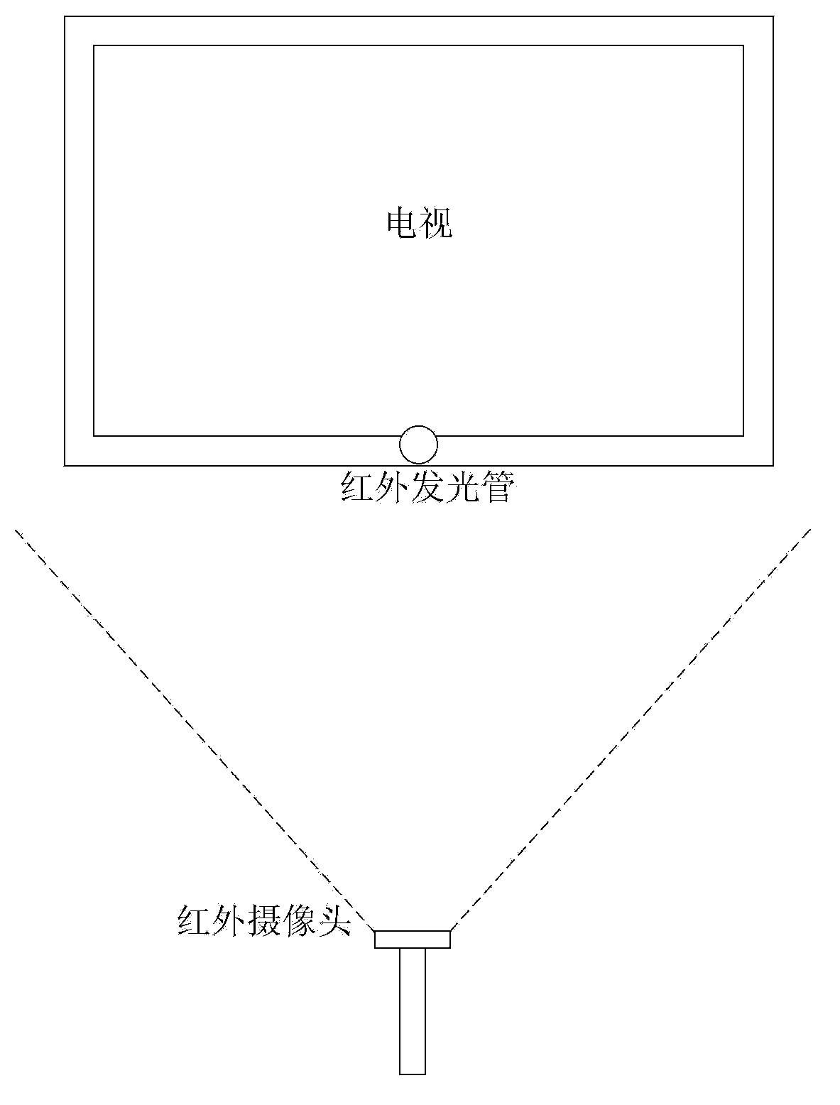
technical field [0001] The invention relates to a control technology, in particular to a control method and electronic equipment. Background technique [0002] With people's increasing requirements for office environment and convenient operation, the popularity of air mouse has also been put on the agenda. The gyroscope air mouse solution can make the traditional mouse break away from the dependence on the desktop, upgrade it to an air mouse, and realize the suspended 3D To operate, just wave your wrist lightly, the pointer can move freely, and control the computer easily. The inventor found that the air mouse realized by using the gyroscope sensor has been unable to overcome the directivity problem, unlike the directivity of the laser pointer, which has the experience of what you point is what you get. [0003] Another air mouse solution is to install an infrared light-emitting tube on the controlled device such as a TV, and install an infrared camera on the remote control...

Claims


Application Information

Patent Timeline
IPC IPC(8): G06F3/0346
Inventor 郑启忠倪绪能
Owner LENOVO (BEIJING) CO LTD
Learn More