Thickness measurement system and thickness measurement method

A thickness measurement and speed detector technology, applied in measurement devices, instruments, error compensation/elimination, etc., can solve the problems of measurement errors and achieve the effect of continuous measurement

Inactive Publication Date: 2014-06-25
KK TOSHIBA
View PDF3 Cites 9 Cited by
  • Summary
  • Abstract
  • Description
  • Claims
  • Application Information

AI Technical Summary

Problems solved by technology

[0007] However, in the thickness measuring device 200 having the above-mentioned structure, as shown in the formula (1), if the distance Lo between the arms 15T and 15B of the C-frame 15 of the...

Method used


Image

  • Thickness measurement system and thickness measurement method
  • Thickness measurement system and thickness measurement method
  • Thickness measurement system and thickness measurement method

Examples


Embodiment Construction

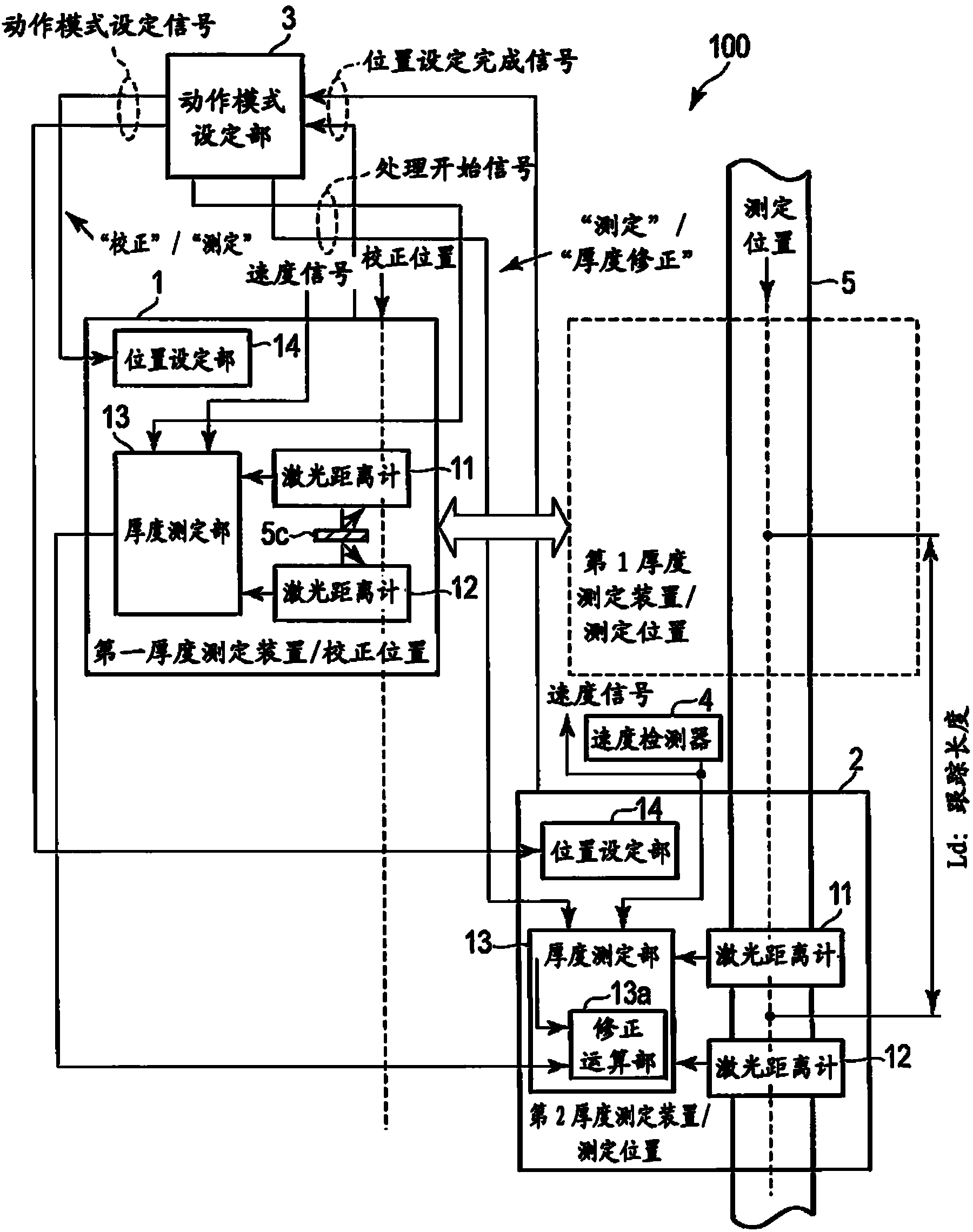
[0028] Below, for the implementation, refer to Figure 1 to Figure 4 Be explained. First, the configuration of the thickness measurement system 100 according to the present embodiment will be described.

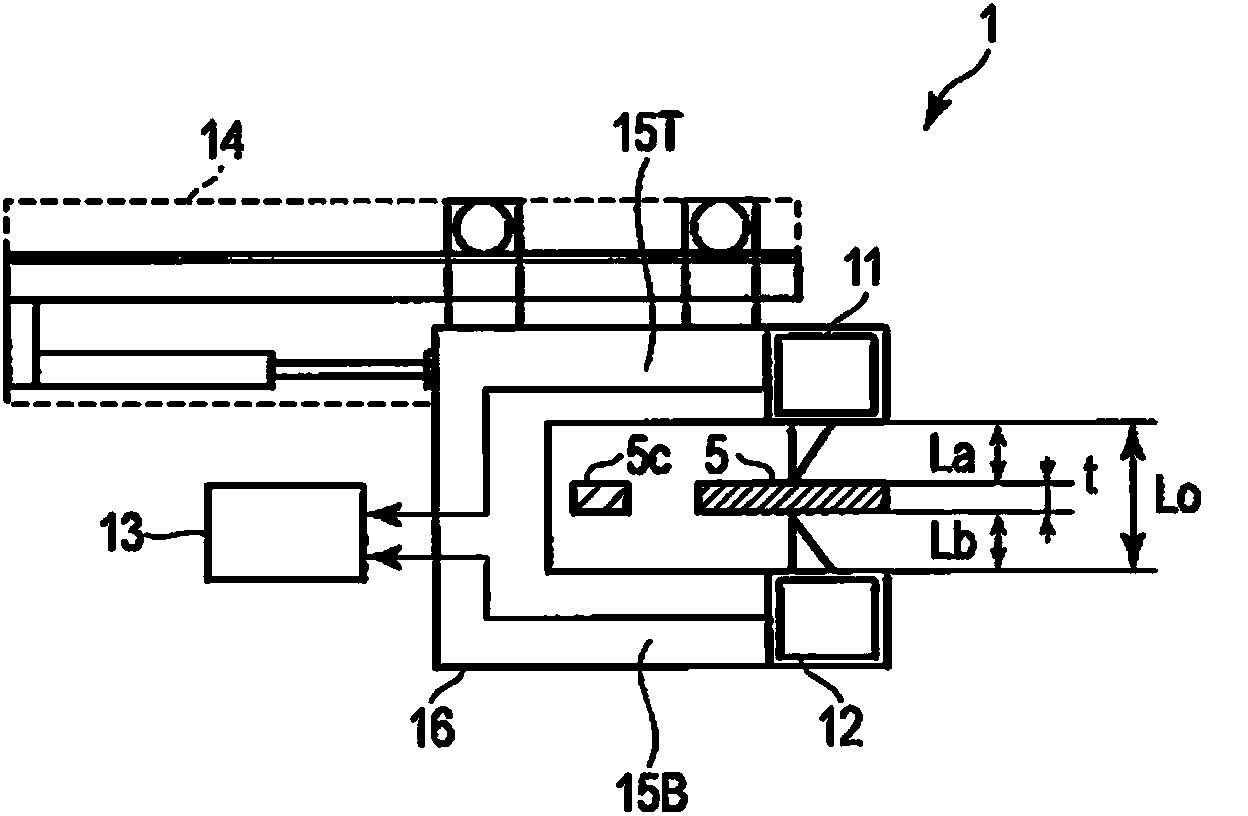
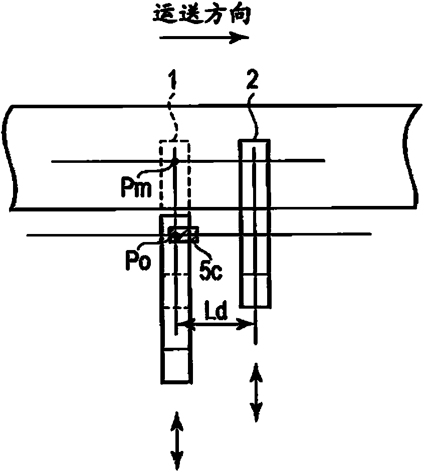
[0029] figure 1 It is a block diagram showing the structure of the thickness measurement system 100 mentioned above. figure 2 From figure 1 It is a cross-sectional view for explaining the structure of the first thickness measuring device 1 or the second thickness measuring device 2 as viewed in the conveying direction of the shown object to be measured (rolled plate) 5 . in addition, image 3 It is a plan view showing a case where the above-mentioned first thickness measuring device 1 and second thickness measuring device 2 are installed at a predetermined interval Ld in the conveying direction of the object to be measured 5 .

[0030] Such as figure 1As shown, the thickness measurement system 100 includes a first thickness measurement device 1 and a second thicknes...


PUM


Abstract

An objective of the present invention is to allow removing the effect of measurement error caused when the distance between support points of a pair of laser rangefinders of a thickness measurement device fluctuates due to temperature changes, and to allow contiguous measurement without special measures being required for safety management. Thickness measurement devices (1, 2) are set with a predetermined gap (Ld), while the first thickness measurement device (1) executes a thickness correction process with a thickness reference plate (5c), and while the second measurement device (2) which is placed on the downstream side of a movement direction executes a measurement process, an operation mode setting unit (3) sets the first thickness measurement device (1) to "measurement", instructs the second thickness measurement device (2) to commence a "thickness correction" process, delays a first thickness measurement value (1) to a location corresponding to a gap in the movement direction, derives the difference between the first thickness measurement value (1) and a second thickness measurement value (2) thereof as a correction value, and executes a thickness correction without interrupting the measurement by the second thickness measurement device (2).

Description

technical field [0001] The present invention relates to a thickness measurement system and a thickness measurement method for measuring the thickness of a plate using a laser distance meter. Background technique [0002] Conventionally, as an apparatus for measuring the thickness of a plate rolled by a rolling mill, a radiation thickness meter using radiation has been mainly used. The radiation thickness meter includes an X-ray thickness meter using X-rays and a γ-ray thickness meter using γ-rays. As the thickness measurement accuracy of these thickness gauges, the accuracy of 0.1% is ensured, and they can be used for quality control related to normal plate thickness without any trouble. [0003] However, since the radiation thickness meter does not narrow the radiation beam system, the spatial resolution is insufficient. In addition, processing for eliminating the influence of noise is required, and this partly slows down the response speed. Therefore, in the radiation t...

Claims


Application Information

Patent Timeline
IPC IPC(8): G01B11/06
CPCG01B11/0691G01B11/06G01B5/0011G01B2210/44
Inventor 古田哲夫石冢照雄
Owner KK TOSHIBA
Why Eureka
Try Eureka