A safe and reliable fire extinguishing launch bracket with long service life
A fire extinguishing launching bracket with long service life technology, which is applied in the field of forest fire extinguishing, and can solve the problems that affect the fire extinguishing launching device retractable and finishing efficiency, the fire extinguishing launching device is not easy to pull out, and the steel nails or tapered columns are easy to be damaged. Potential safety hazard, simple and convenient operation, convenient retractable effect
- Summary
- Abstract
- Description
- Claims
- Application Information
AI Technical Summary
Problems solved by technology
Method used
Image
Examples
Embodiment 1
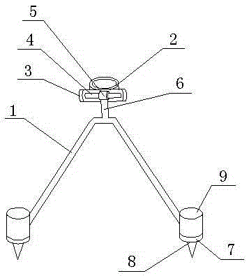
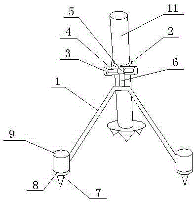
[0016] Such as figure 1 , figure 2 As shown, a safe, reliable and long-life fire extinguishing launch bracket described in this embodiment includes a support rod 1, a collar 2, a U-shaped groove 3, a transverse shaft 4, a sleeve 5 and a connecting rod 6, and the collar 2 is socketed on the gun barrel 11, the U-shaped groove 3 is fixed on the outer surface of the collar 2, the transverse shaft 4 is fixed in the U-shaped groove 3, the sleeve 5 is connected on the transverse shaft 4, and the sleeve 5 and The connecting rod 6 is fixedly connected, the connecting rod 6 is fixedly connected with the supporting rod 1, the supporting rod 1 is a V-shaped structure, the midpoint of the supporting rod 1 is fixedly connected with the connecting rod 6, and a ring is provided at both ends of the supporting rod 1 7. A hydraulic cylinder 9 is fixed on the ring 7, the piston rod of the hydraulic cylinder 9 passes through the ring 7 downward, and the front end of the piston rod of the hydraul...
Embodiment 2
[0019] In this embodiment, on the basis of Embodiment 1, the position angle of the ring 7 is defined as follows: the angle between the plane where the ring 7 is located and the plane where the support rod 1 is located in this embodiment is 40 to 70 degrees, and the invention After a lot of research, people have found that the angle between the ring 7 and the support rod 1 has an influence on the fixing of the bracket and the force of the insertion rod 8. When the plane where the ring 7 is located and the plane where the support rod 1 is located When the included angle is in the range of 40-70 degrees, not only the bracket is fixed more firmly, but also the force of the insertion rod 8 is more reasonable, which facilitates the retraction of the insertion rod 8 and avoids affecting the use of the bracket.
Embodiment 3
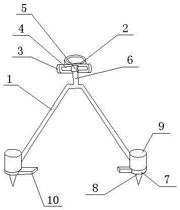
[0021] Such as image 3 As shown, in this embodiment, on the basis of Embodiment 1, a pedal 10 is set on the ring 7, and the pedal 10 is located between the two rings 7, which can further facilitate the insertion of the insertion rod 8. By stepping on the pedal 10, The insertion rod 8 can be quickly inserted into the ground, and at the same time, the pedal 10 is located between the two rings 7, so that the force of the insertion rod 8 and the entire bracket is more reasonable, avoiding affecting the use of the bracket, and benefiting the service life of the bracket.
PUM
 Abstract
Description
Claims
Application Information
 - R&D
- Intellectual Property
- Life Sciences
- Materials
- Tech Scout
- Unparalleled Data Quality
- Higher Quality Content
- 60% Fewer Hallucinations
Browse by: Latest US Patents, China's latest patents, Technical Efficacy Thesaurus, Application Domain, Technology Topic, Popular Technical Reports.
© 2025 PatSnap. All rights reserved.Legal|Privacy policy|Modern Slavery Act Transparency Statement|Sitemap|About US| Contact US: help@patsnap.com


