
Floating-type oil absorption device of oil-water separator

An oil-water separator, floating technology, applied in the direction of liquid separation, separation methods, chemical instruments and methods, etc., can solve the problems of polluting the furnace, soft spots of parts, affecting the appearance of workpieces, etc., to prevent the entry of air and impurities, and facilitate Installation and disassembly, the effect of a high degree of automation

Inactive Publication Date: 2014-07-02
HEPHAES HEAT TREATMENT SYST JIANGSU
View PDF6 Cites 12 Cited by
  • Summary
  • Abstract
  • Description
  • Claims
  • Application Information

AI Technical Summary

Problems solved by technology

Because the insertion depth of the suction pipe is difficult to grasp, if it is too shallow, air suction will occur, and air or magazines will be mixed into the oil suction port, which will affect the separation effect; if it is too deep, water will be sucked into the container, so this form of oil-water separator. Oil often contains a certain amount of water, and the complete separation of oil and water cannot be achieved.
When using water containing oil to clean the workpiece, the cleaning will not be clean, and the next tempering process will produce a lot of oily smoke, which will not only affect the appearance of the workpiece, but also pollute the tempering furnace and affect the quality of tempering
When using the separated oil for secondary use, if the oil contains too much water, it will affect the heat treatment effect, causing soft spots, quenching cracks or deformation of the parts, or oil splashing, resulting in safety accidents

Method used


Image

  • Floating-type oil absorption device of oil-water separator

Examples


Embodiment 1)

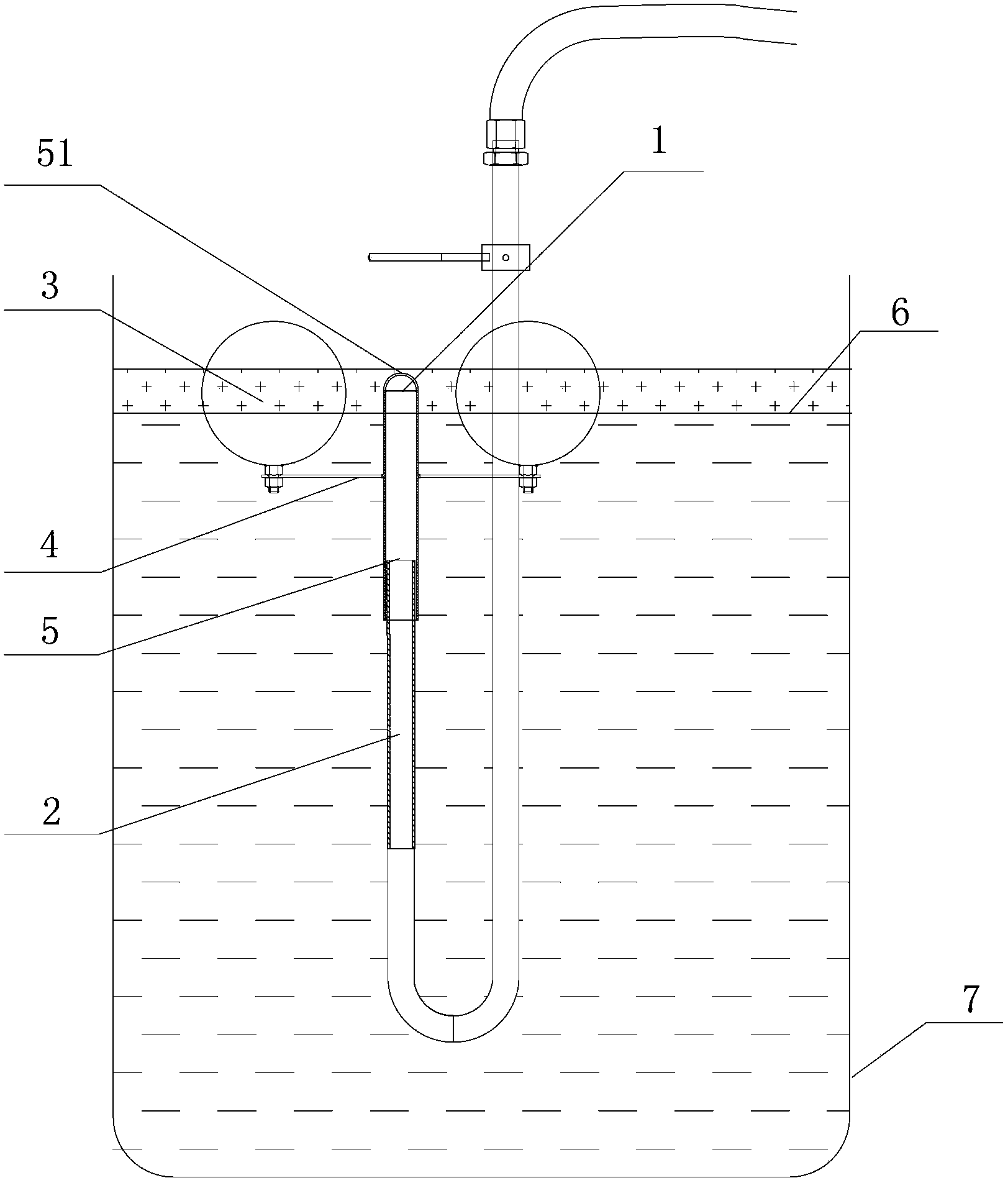
[0017] See figure 1 , the present invention has an oil suction port 1, an oil suction pipe 2, two stainless steel floating balls 3 and a connecting rod 4 located at the lower end of the stainless steel floating balls and fixedly connected thereto; The oil suction sleeve 5 is slidingly connected with the oil suction pipe 2, fixedly connected with the middle part of the connecting rod 4, and the other end of the oil suction pipe is connected with the oil suction starting device.

[0018] In order to prevent water from entering the pipeline from the port of the oil suction pipe 2, preferably, the oil suction sleeve 5 and the oil suction pipe 2 are cylindrical, the diameter of the oil suction sleeve 5 is larger than that of the oil suction pipe 2, and the oil suction pipe 2 is inserted in the oil suction sleeve 2. The upper end of the oil suction port 1 is provided with an arc-shaped baffle 51 to prevent the oil suction pipe 2 from passing through the oil suction sleeve 5 .

[00...


PUM


Abstract

The invention relates to an oil absorption device, in particular to a floating-type oil absorption device of an oil-water separator. The oil absorption device comprises an oil absorption hole, an oil absorption pipe, two stainless steel floating balls, a connecting rod which is arranged on the lower ends of the two stainless steel floating balls and fixedly connected with the two stainless steel floating balls, and an oil absorption sleeve, wherein the oil absorption hole is arranged on the top end of the oil absorption sleeve, the oil absorption sleeve is connected with the oil absorption pipe in a sliding manner and fixedly connected with the middle part of the connecting rod, and the other end of the oil absorption pipe is connected with an oil absorption starting device. The oil absorption sleeve is connected with the oil absorption pipe in a sliding manner, and can move up and down along the floating balls, so that an oil-water interface can be automatically and precisely tracked, the horizontal height of an oil-water inlet can be consistent with the oil-water interface, the substance entering the pipeline is basically oil, air and impurities can be prevented from entering, the separation effect is good, the automation degree is high, and simplicity and convenience in operation can be realized.

Description

technical field [0001] The invention relates to an oil absorbing device, in particular to a floating oil absorbing device for an oil-water separator. Background technique [0002] The oil-water separator is a device that uses the principle of gravity sedimentation to remove oil in water according to the specific gravity of oil and water, and they are not compatible. In the existing oil-water separator, the suction pipe is inserted into the oil-water mixed liquid, and the oil (including water) is sucked into the container by the action of the pump. Because the insertion depth of the suction pipe is difficult to grasp, if it is too shallow, air suction will occur, and air or magazines will be mixed into the oil suction port, which will affect the separation effect; if it is too deep, water will be sucked into the container, so this form of oil-water separator. Oil often contains a certain amount of water, and the complete separation of oil and water cannot be achieved. When ...

Claims


Application Information

Patent Timeline
Patent Type & Authority Applications(China)
IPC IPC(8): B01D17/032
Inventor 杨爱斌李哨国华公平
Owner HEPHAES HEAT TREATMENT SYST JIANGSU
Learn More