pneumatic tire

A technology for pneumatic tires and tires, which is applied to heavy-duty tires, tire parts, tire treads/tread patterns, etc., and can solve the problems of reducing the volume of lateral grooves and poor drainage performance, etc.

Active Publication Date: 2016-11-02
SUMITOMO RUBBER IND LTD
View PDF6 Cites 0 Cited by
  • Summary
  • Abstract
  • Description
  • Claims
  • Application Information

AI Technical Summary

Problems solved by technology

[0003] However, in the above-mentioned pneumatic tire, the groove volume of the lateral groove is reduced due to the reinforcement of the rib, and the drainage performance is deteriorated.
In addition, if the wear of the blocks progresses further, the lateral grooves are interrupted, so there is a problem that the drainage performance deteriorates especially at the end of the wear.

Method used


Image

  • pneumatic tire
  • pneumatic tire
  • pneumatic tire

Examples


Embodiment

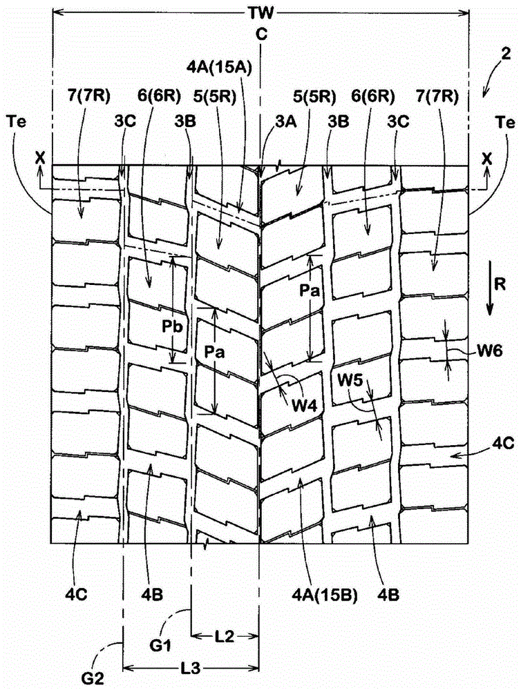
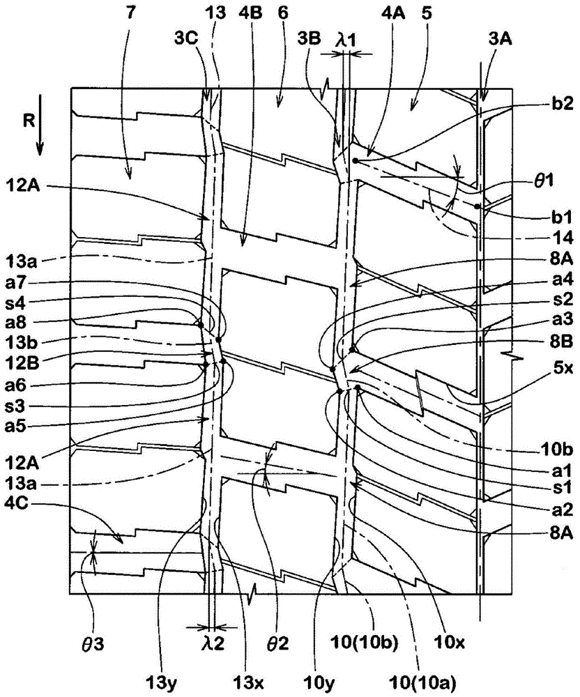
[0066] In order to confirm the effect of the present invention, the figure 1 The test was carried out on a 11.00R20 heavy-duty pneumatic tire with a basic pattern and based on the specifications in Table 1. In addition to the grooves listed in Table 1, the groove width and angle of each groove are as follows: figure 1 shown. In addition, the main common specifications of each tire are as follows.

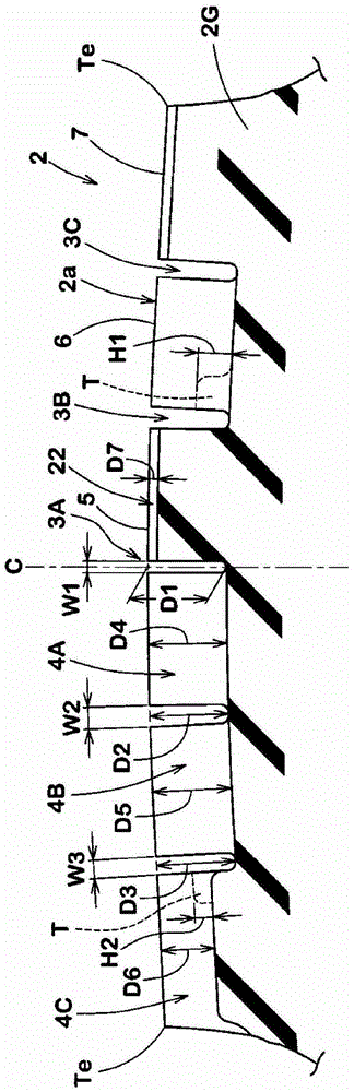
[0067] Tread contact width TW: 242.4mm

[0068] Groove depth of each main groove: 21.0mm

[0069] Groove depth of central transverse groove: 21.0mm

[0070] The groove depth of the middle horizontal groove: 21.0mm

[0071] The groove depth of the shoulder: 14.5mm

[0072] Groove depth of fine groove: 2.0mm

[0073] The test method is as follows.

[0074]

[0075] Each test tire was mounted on all wheels of a Japanese-made truck (2-D vehicle, ABS brake mounted) with a load capacity of 8 t under the following conditions. Then, the test driver drove the test vehicle on a tes...


PUM


Abstract

The present invention relates to a pneumatic tire which evenly increases draining performance and anti-wear performance. On the tire tread (2) is provided with: a central main channel (3A), an intermediate principal sulcus (3B), a tire shoulder main channel (3C), a central groove crossing channel (4A), an intermediate transverse groove (4B) and a tire shoulder transverse groove (4C). The intermediate transverse groove (4B) and the tire shoulder transverse groove (4C) are approximately in linear extension and their channel widths range between 4 -16.0mm. At the bottoms of the intermediate transverse groove (4B) and the tire shoulder transverse groove (4C) are provided reinforced steel the depth of which is no less than 50% (T). After the central block (5), the central region of the ends of the (5A) land ratio after the middle block (6) at both ends of the middle region (6A) of the land is 1.05 -1.25 times. The central groove crossing channel (4A) with respect to the tire axial angle has an angle 15 -45 degrees which is larger than that of the middle transverse groove (4B) with respect to the tire axial angle.

Description

technical field [0001] The present invention relates to a pneumatic tire having improved drainage performance and wear resistance in a balanced manner. Background technique [0002] Conventionally, there are pneumatic tires in which a plurality of blocks are defined in a tread portion by a plurality of main grooves extending in the tire circumferential direction and a plurality of lateral grooves extending in the tire axial direction. In recent years, for the purpose of improving the wear resistance of such a pneumatic tire, a tie bar protruding from the deepest groove bottom of the lateral groove is provided in the lateral groove. When the tire rolls, the ribs restrain the tire circumferential movement of the blocks, thereby reducing the amount of slip produced by the blocks. [0003] However, in the pneumatic tire as described above, the groove volume of the lateral grooves is reduced by the tensioning of the ribs, thereby degrading the drainage performance. In addition,...

Claims


Application Information

Patent Timeline
Patent Type & Authority Patents(China)
IPC IPC(8): B60C11/03B60C11/12
CPCB60C11/1369B60C2200/06
Inventor 前原敦史
Owner SUMITOMO RUBBER IND LTD
Why Eureka
Try Eureka