Gearshift mounting plate and gearshift mounting structure

A technology of shifting mechanism and installation structure, which is applied in the direction of control device, transportation and packaging, vehicle parts, etc., can solve the problems of complex product process and high cost, and achieve the effects of reduced manufacturing difficulty, good strength and rigidity, and low manufacturing cost.

Inactive Publication Date: 2014-07-02
CHONGQING CHANGAN AUTOMOBILE CO LTD
View PDF5 Cites 4 Cited by
  • Summary
  • Abstract
  • Description
  • Claims
  • Application Information

AI Technical Summary

Problems solved by technology

If the H-point of the vehicle body is arranged higher, the gearshift mechanism directly installed on the front floor assembly cannot meet the driver's shifting requirements. Meet the manufacturing process feasibility, such as Figure 5 , Image 6 , Figure 7 As shown, the middle passage is divided into two parts, the front section 6 of the middle passage and the rear section 7 of the middle passage. On the front section 6 of the channel, in this case, the size of the middle channel is usually made very large. At the same time, it is necessary to add reinforcements for local reinforcement to meet the requirements of the shift mechanism for the rigidity and strength of the installation point. Therefore, there is a product process complex and costly issues

Method used


Image

  • Gearshift mounting plate and gearshift mounting structure
  • Gearshift mounting plate and gearshift mounting structure
  • Gearshift mounting plate and gearshift mounting structure

Examples


Embodiment Construction

[0020] The present invention will be further described below in conjunction with accompanying drawing:

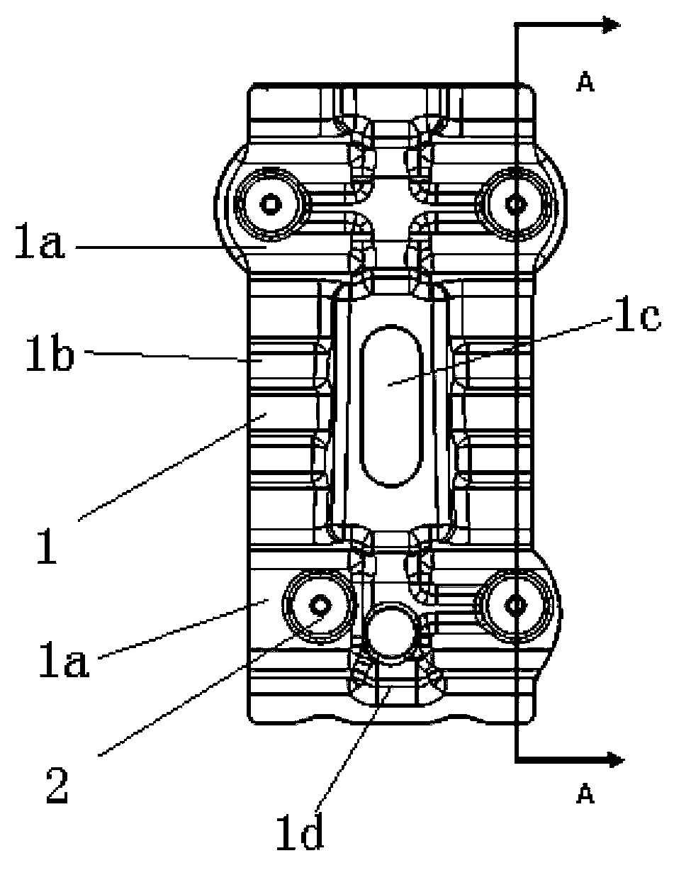
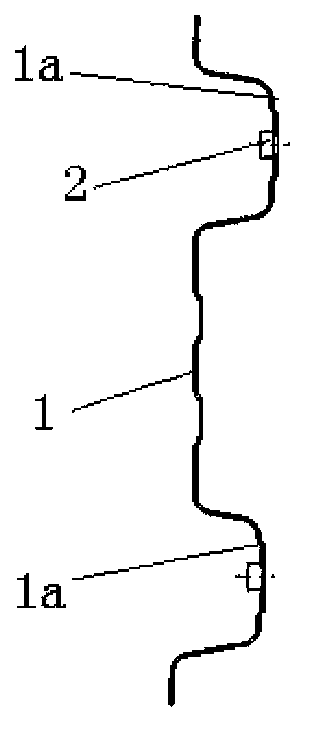
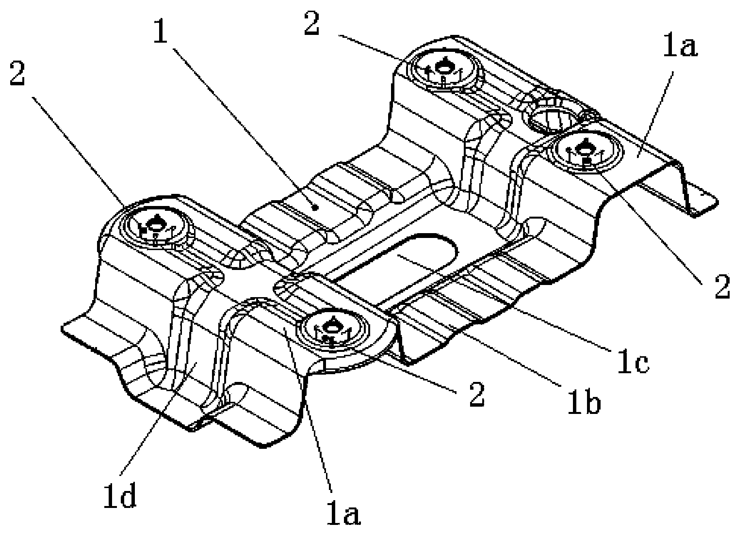
[0021] Such as Figure 1 to Figure 3 The shifting mechanism mounting plate shown includes a mounting plate body 1 and four projection welding nuts 2. The mounting plate body 1 is a stamped sheet metal part. On the gear mechanism installation surface 1a, four projection welding nuts 2 are welded on the gear shift mechanism installation surface 1a, and are located below the gear shift mechanism installation surface 1a. A lightening hole 1c is opened in the middle of the mounting plate body 1, which reduces the weight of the mounting plate of the shifting mechanism. A transverse reinforcing rib 1b and a longitudinal reinforcing rib 1d are arranged on the mounting plate of the shifting mechanism, which improves the rigidity and strength of the mounting plate of the shifting mechanism.

[0022] Such as Figure 4 As shown, the installation structure of the shifting mechanism o...


PUM


Abstract

The invention discloses a gearshift mounting plate comprising a mounting plate body which is a sheet metal stamped part. The mounting plate body is provided with a raised gearshift mounting face. A projection welded nut is welded on the gearshift mounting face. The invention further discloses a gearshift mounting structure comprising a gearshift, a middle channel reinforcing plate and the gearshift mounting plate. The gearshift mounting plate comprises a mounting plate body made by sheet metal stamping. The mounting plate body is provided with the raised gearshift mounting face. The projection welded nut is welded on the gearshift mounting face. The gearshift is fixedly mounted on the middle channel reinforcing plate through the projection welded nut on the gearshift mounting plate and a bolt. The mounting height of the gearshift can be increased while the requirements of a gearshift mounting spot for rigidity and strength are met.

Description

technical field [0001] The invention belongs to the automobile body technology, and in particular relates to a shift mechanism mounting plate. Background technique [0002] In modern automobile body design, the fixed point of the shift mechanism is usually arranged on the front panel assembly or the front floor assembly. Usually, the height of this fixed point is very low, which can easily meet the requirements of the shift mechanism on the fixed point. Rigidity and strength requirements. Sometimes a reinforcing plate is added to the lower part of the central channel of the front floor or the front wall to meet the requirements of the shift mechanism for the rigidity and strength of the fixed point. If the H-point of the vehicle body is arranged higher, the gearshift mechanism directly installed on the front floor assembly cannot meet the driver's shifting requirements. Meet the manufacturing process feasibility, such as Figure 5 , Image 6 , Figure 7 As shown, the mid...

Claims


Application Information

Patent Timeline
Patent Type & Authority Applications(China)
IPC IPC(8): B60K20/04
Inventor 王有传蔡睿尚广先
Owner CHONGQING CHANGAN AUTOMOBILE CO LTD
Why Eureka
Try Eureka