Ship electric servo fin/wing optional-angle-ratio transmission device

A transmission device and electric servo technology, applied in the direction of steering gear, ship parts, ship construction, etc., can solve the problems that do not involve the ship's electric servo fin/wing fin arbitrary rotation angle ratio transmission device, etc., to improve the hydrodynamic performance of the fin, energy The effect of reducing consumption and reducing the range of motion

Inactive Publication Date: 2014-07-02
HARBIN ENG UNIV
View PDF7 Cites 6 Cited by
  • Summary
  • Abstract
  • Description
  • Claims
  • Application Information

AI Technical Summary

Problems solved by technology

The patent application number is 200710071664.7, and the patent application document named "Ship fin and rudder comprehensive coordination control device" discloses a fin / wing rudder comprehensive coordination control device, but only provides the principle block diagram of the control; the patent application No. 200910071807.3, the patent application document titled "ship rudder / wing rudder-fin / wing fin joint control method" discloses a joint control method, but none of them involves the ship's electric servo fin / wing fin arbitrary rotation angle ratio transmission device

Method used


Image

  • Ship electric servo fin/wing optional-angle-ratio transmission device
  • Ship electric servo fin/wing optional-angle-ratio transmission device
  • Ship electric servo fin/wing optional-angle-ratio transmission device

Examples


Embodiment Construction

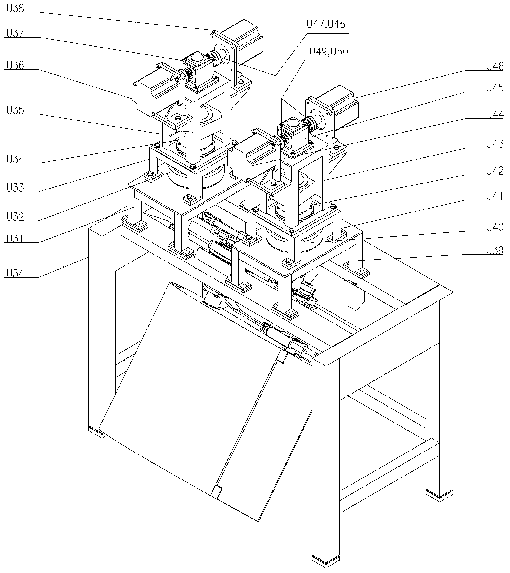
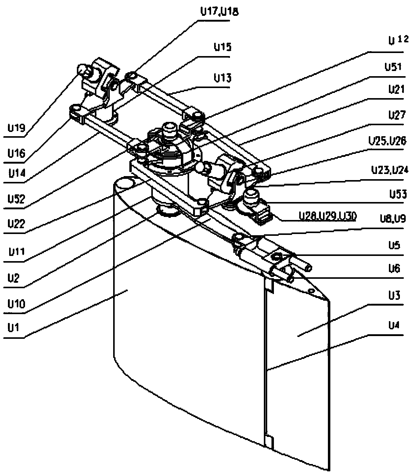
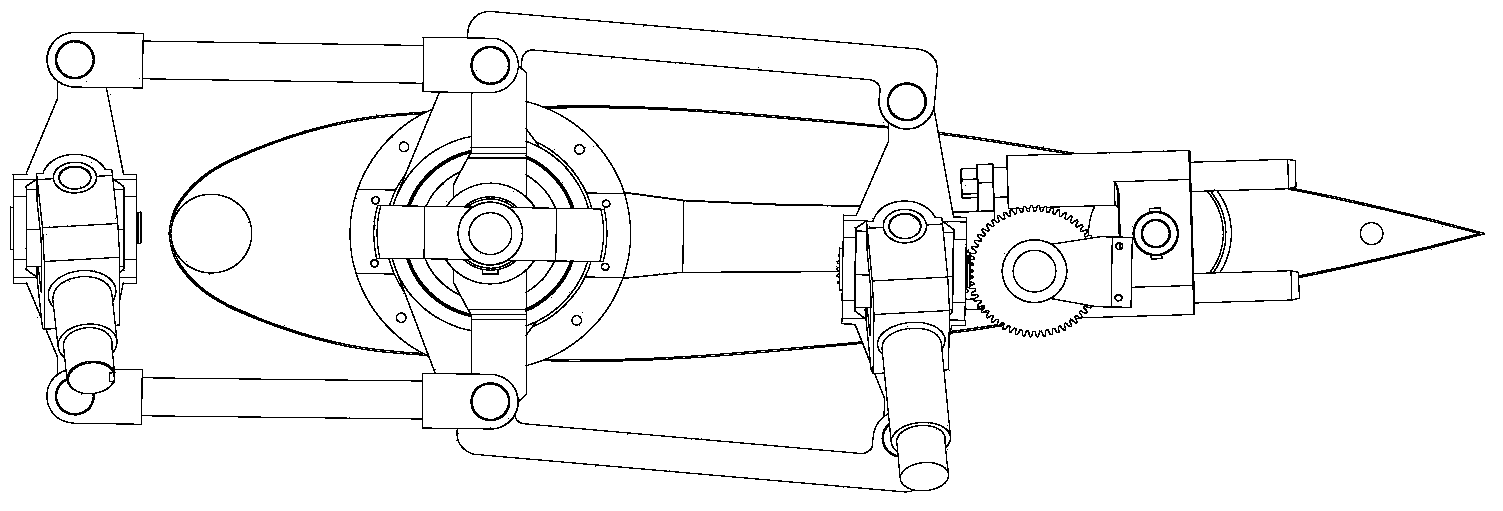
[0017] The present invention is described in more detail below in conjunction with accompanying drawing example:

[0018] combine Figure 1~4 , the present invention is a marine electric servo fin / wing fin arbitrary rotation angle ratio transmission device, which includes a power device and a transmission device installed on the fin mounting plate and bracket U54. When the main fin motors U36 and U38 rotate, their rotation is reduced U37, U34, and after being loaded by the magnetic powder brake, it drives the universal joint shaft handle U19 of the main fin to rotate. When the universal joint shaft U19 of the main fin rotates counterclockwise, the universal joint arm U16 of the main fin also rotates counterclockwise. , the main fin push-pull rods U13 and U14 drive the main fin rocker U12 to rotate counterclockwise, so that the main fin shaft U2 rotates counterclockwise, that is, the main fin blade U1 rotates counterclockwise at this time; if the main fin shaft U2 rotates count...


PUM


Abstract

The invention provides a ship electric servo fin/wing optional-angle-ratio transmission device. When a main fin motor rotates, a cardan shaft handle of a main fin is driven to rotate; when the cardan shaft handle of main fin rotates counterclockwise, a pulling and pushing rod of the main fin drives a main fin swing arm to rotate counterclockwise to allow a main fin shaft to rotate counterclockwise, that is to say, a main fin blade rotates counterclockwise; when the main fin shaft rotates counterclockwise, a wing motor is driven to rotate, that is to say, a wing cardan shaft handle and a wing cardan shaft handle connecting lever rotate to drive a wing pulling and pushing rod, a wing rotating sleeve connecting lever is driven to drive a wing rotating sleeve to rotate, and a wing swing connecting lever is driven to swing and drive a wing slide rod and a wing slide rod dual-hole sleeve to swing. Since a wing shaft penetrates the main fin blade and is fixed to the wing slide rod dual-hole sleeve, the rotating angle of a wing blade is increased or decreased on the basis of an existing wing angle, and the wing blade is allowed to rotate without limit of the main fin blade. By the aid of the ship electric servo fin/wing optional-angle-ratio transmission device, the swing reducing capability of a fin stabilizing system can be improved greatly.

Description

technical field [0001] The invention relates to a ship device, in particular to an attitude control anti-rolling device for the ship device. Background technique [0002] In a certain range and at the same angle, the lift value that the fin stabilizer can achieve will increase with the increase of camber, and the lift-to-drag ratio will also be improved to a certain extent. Taking advantage of this characteristic, flap fins (fins / wing fins) of ships have been designed to improve the hydrodynamic performance of the fins. In a broad sense, the wing fin is equivalent to a wing with variable camber, which can provide greater lift at the same main fin angle before the incoming flow separates, which greatly improves the maneuverability and seakeeping performance of the ship. At the same time, at the zero position, the entire fin presents a symmetrical wing profile, which reduces resistance and ensures the sailing stability of the ship when sailing straight. Therefore, research on...

Claims


Application Information

Patent Timeline
Patent Type & Authority Applications(China)
IPC IPC(8): B63H1/36B63H25/00
Inventor 宋颖慧刘胜李冰张兰勇王宇超
Owner HARBIN ENG UNIV
Why Eureka
Try Eureka