

Floating wind-hydraulic power generating set
A hydroelectric power generation device, floating sea-type technology, applied in the direction of wind power generation, wind engine, wind motor combination, etc., to achieve the effect of convenient expansion of power generation capacity and change of area size
- Summary
- Abstract
- Description
- Claims
- Application Information
AI Technical Summary
Problems solved by technology
Method used
Image

Examples
Embodiment Construction
[0018] The present invention is described in more detail below in conjunction with accompanying drawing example:
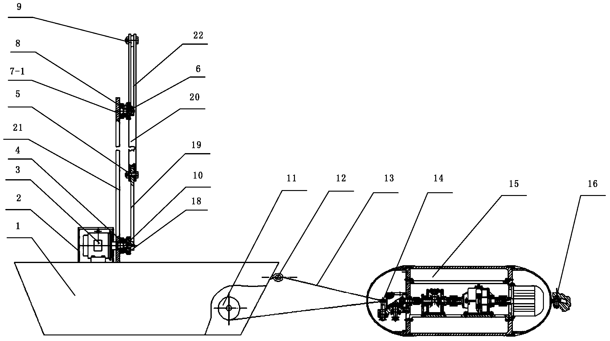
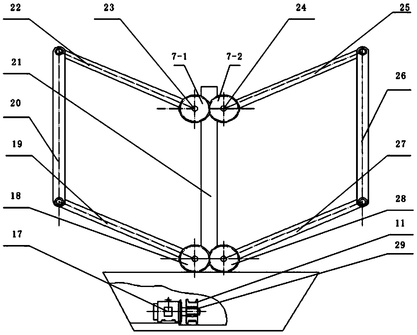
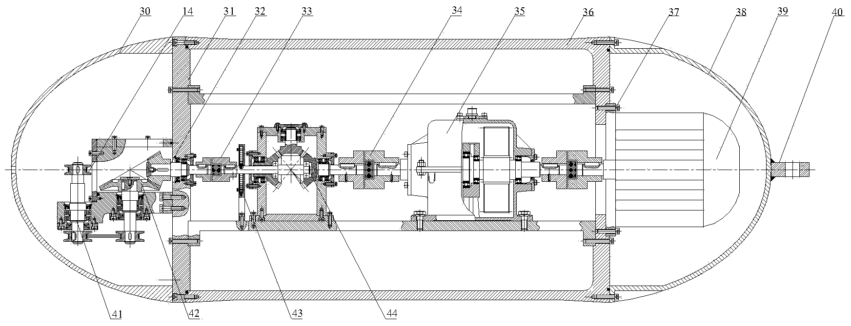
[0019] combine Figure 1~3 , the present invention is a kind of sea-floating wind-hydroelectric power generation device, which is composed of hull, column frame, sail opening and closing mechanism, rope stretching unit, power generation unit and other parts. The power generation unit is fixed on the shore foundation (or fixed carrier), and the hull floats on the sea; the column frame is fixed on the hull by bolts, and the column frame provides installation support for the sail opening and closing mechanism, and the rope tension unit connects the hull and the power generation unit . The sail opening and closing mechanism mainly includes the opening and closing motor, the sealing cover of the opening and closing motor, bearings, driving gears, driven gears, auxiliary gears, two sets of linkage mechanisms, etc. The driving rods of the two sets of linkage mechanisms...
PUM
 Abstract
Description
Claims
Application Information