
A floating sea wind hydroelectric power generation device

A hydroelectric power generation device, floating sea type technology, applied in the direction of wind power generation, wind engine, wind motor combination, etc., to achieve the effect of changing the size of the area and facilitating the expansion of power generation capacity

Inactive Publication Date: 2016-11-23
HARBIN ENG UNIV
View PDF8 Cites 0 Cited by
  • Summary
  • Abstract
  • Description
  • Claims
  • Application Information

AI Technical Summary

Problems solved by technology

At present, the two independent power generation methods are relatively perfect, but there are few people who combine the two methods together.

Method used


Image

  • A floating sea wind hydroelectric power generation device
  • A floating sea wind hydroelectric power generation device
  • A floating sea wind hydroelectric power generation device

Examples


Embodiment Construction

[0018] The present invention is described in more detail below in conjunction with accompanying drawing example:

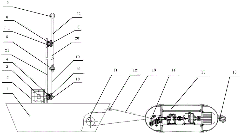
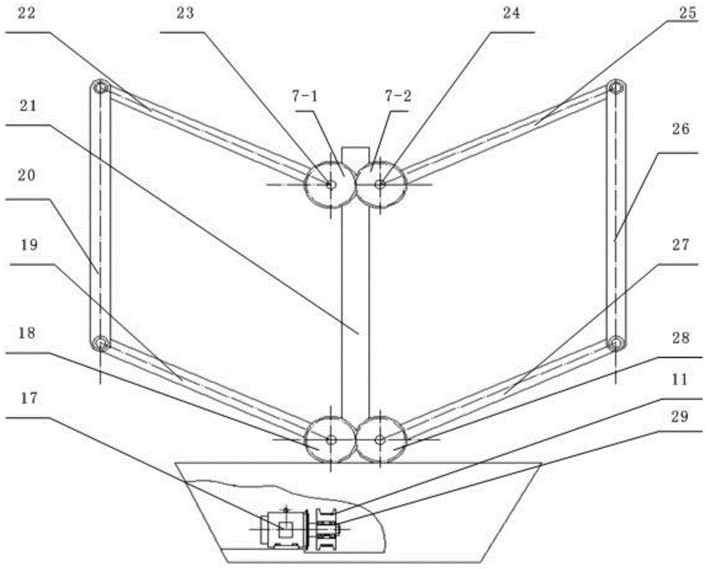
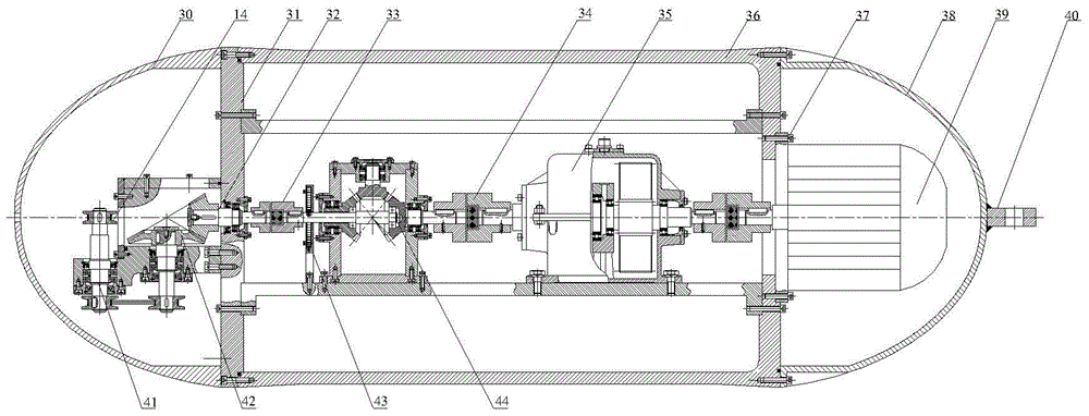
[0019] to combine Figure 1~3 , the present invention is a kind of sea-floating wind-hydroelectric power generation device, which is composed of hull, column frame, sail opening and closing mechanism, rope stretching unit, power generation unit and other parts. The power generation unit is fixed on the shore foundation (or fixed carrier), and the hull floats on the sea; the column frame is fixed on the hull by bolts, and the column frame provides installation support for the sail opening and closing mechanism, and the rope tension unit connects the hull and the power generation unit . The sail opening and closing mechanism mainly includes the opening and closing motor, the sealing cover of the opening and closing motor, bearings, driving gears, driven gears, auxiliary gears, two sets of linkage mechanisms, etc. The driving rods of the two sets of linkage mechani...


PUM


Abstract

The invention aims to provide a floating wind-hydraulic power generating set comprising a boat, a column frame, a sail opening-closing mechanism, a rope tension unit, and a generating unit. The column frame is fixed to the boat which floats on the sea. The generating unit is fixed toe a fixed shore base or fixed carrier. The column frame is connected with the sail opening-closing mechanism. One end of the rope tension unit is connected with the boat; the other end of the rope tension unit is connected with the generating unit. When the floating wind-hydraulic power generating set is in use, the sail opening-closing mechanism opens, the boat leaves the generating unit under the action of wind load and water flow, the rope tension unit drives a drive wheel of the generating unit to rotate, and power generation is achieved; when a regulated travel is reached, the sail opening-closing mechanism closes, a motor on the boat operates and tensions ropes, and the boat approaches to the generating unit. The floating wind-hydraulic power generating set has the advantages that generating efficiency is improved and capacity of the generating set can be expanded conveniently by changing the structural size of a sail.

Description

technical field [0001] The invention relates to a power generating device. Background technique [0002] With the development of our country's economy and the advancement of science and technology, the demand for electric energy continues to increase. Therefore, power generation assembly with high energy saving and environmental protection efficiency has become an urgent need for our country. In traditional wind power generation, the fan directly drives the generator to generate electricity through simple mechanical speed change; while in hydropower generation, the flow of water or water level difference drives the generator to generate electricity. Due to the large uncertainty in the size and direction of the wind, the efficiency of wind turbines is not very high; while hydropower generation requires a large water level difference and its cost is relatively high. At present, the two independent power generation methods are relatively perfect, but few of them combine the tw...

Claims


Application Information

Patent Timeline
Patent Type & Authority Patents(China)
IPC IPC(8): F03D9/25F03D15/10F03B13/00
CPCY02E10/72
Inventor 张立勋梁迎彬陈志明朱海涛王晓宇
Owner HARBIN ENG UNIV
Learn More