Moving motor and electric vehicle

An electric motor and kinetic energy technology, applied in the field of electric motors and electric vehicles, can solve the problems of poor battery life, frequent charging, and limited number of electric vehicle charging stations, so as to save fuel, improve battery life, and avoid traffic accidents.

Inactive Publication Date: 2013-09-04
任宝全
View PDF3 Cites 7 Cited by
  • Summary
  • Abstract
  • Description
  • Claims
  • Application Information

AI Technical Summary

Problems solved by technology

[0003] Although the environmental protection performance of electric vehicles is unquestionable, the electric vehicles currently in use face many problems, the main problem of which is that the existing electric vehicles have poor battery life, need to be charged frequently to travel long distances, and need to be...

Method used


Image

  • Moving motor and electric vehicle
  • Moving motor and electric vehicle

Examples


Embodiment 1

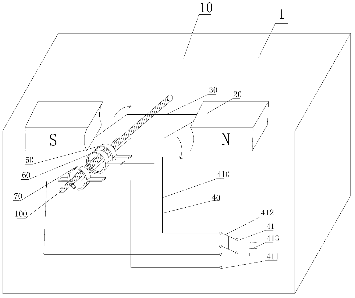
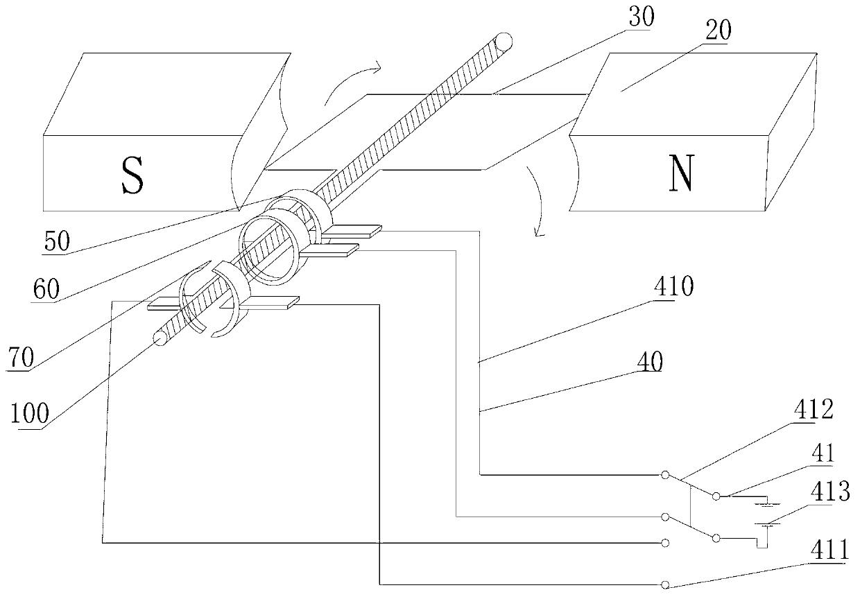
[0042] See figure 1 with figure 2 , The first embodiment of the present invention provides an electric motor 1, including a housing 10 and a magnetic field generator 20, a motor coil 30, a bidirectional control circuit 40, a first slip ring, and a carbon brush assembly 50 arranged inside the housing 10, The second slip ring and carbon brush assembly 60 and the third slip ring and carbon brush assembly 70;

[0043] Wherein, it should be noted that, as an implementation manner, the motor coil is a rectangular motor coil;

[0044] The magnetic field generating device 20 is used to generate a magnetic field effect;

[0045] The motor coil 30 is located between the N pole and the S pole of the magnetic field generating device 20;

[0046] The bidirectional control circuit 40 includes a main circuit 41 and a first branch 410 and a second branch 411 connected in parallel with each other; a bidirectional control switch 412 and a battery 413 are connected in series on the main circuit 41; th...

Embodiment approach

[0056] Preferably, as an implementable manner, the magnetic field generating device 20 includes a pair of permanent magnets;

[0057] The motor coil is located between the N pole of one permanent magnet in the pair of permanent magnets and the S pole of the opposite permanent magnet.

[0058] Preferably, as another possible implementation manner, the magnetic field generating device 20 includes an excitation winding through which an excitation current is passed.

[0059] The motor coil is located between the N pole and the S pole generated by the field winding.

[0060] Further, the electric motor 1 further includes a first voltage regulating device (not shown);

[0061] The first voltage regulating device is connected in series to the first branch 410;

[0062] The first voltage regulating device is used to adjust the output current of the first branch to adapt to the battery charging.

[0063] Further, the electric motor 1 further includes a second voltage regulating device (not shown);...

Embodiment 2

[0070] Correspondingly, on the basis of the electric motor provided in the first embodiment of the present invention, the second embodiment of the present invention also provides an electric vehicle, including a kinetic energy collection device and the above-mentioned electric motor;

[0071] The kinetic energy collection device includes a kinetic energy collection component and a transmission shaft;

[0072] The kinetic energy collection component is used to collect kinetic energy, and use the kinetic energy to drive the transmission shaft to rotate;

[0073] The transmission shaft is connected with a rotating shaft key on the moving motor.

[0074] Analyzing the structure of the above electric vehicle, it can be seen that when the power generation function is realized, the transmission shaft on the kinetic energy acquisition device drives (indirect drive) the rotating shaft to rotate to realize power generation and charge the battery on the power generation branch; when the motor fun...


PUM


Abstract

The invention discloses a moving motor and an electric vehicle. The moving motor comprises a shell, and a magnetic field generating device, a motor coil, a bidirectional control circuit, a first slip ring and carbon brush assembly, a second slip ring and carbon brush assembly and a third slip ring and carbon brush assembly arranged inside the shell, which are arranged inside the shell, wherein the magnetic field generating device is used for generating a magnetic field effect; the motor coil is positioned between the N pole and S pole of the magnetic field generating device; the bidirectional control circuit comprises a main path, and a first branch and a second branch which are connected with each other in parallel; a bidirectional control switch and a storage battery are connected in series to the main path; the bidirectional control switch is used for controlling the first branch or the second branch to be closed; the first slip ring and carbon brush assembly and the second slip ring and carbon brush assembly are connected in series to the first branch; a first terminal on the motor coil is electrically connected with the first slip ring and carbon brush assembly; a second terminal on the motor coil is electrically connected with the second slip ring and carbon brush assembly; the third slip ring and carbon brush assembly is connected in series to the second branch; and a third terminal on the motor coil is electrically connected with the two ends of the third slip ring and carbon brush assembly.

Description

Technical field [0001] The present invention relates to the technical field of electric motors, in particular to an electric motor and an electric vehicle. Background technique [0002] In the development of human society, while the development of social science and technology is constantly advancing, some social contradictions have also emerged, such as pollution problems. Among them, the existing pollution problems mainly stem from the exhaust emissions of electric vehicles. In order to solve the exhaust gas With regard to emission issues, countries around the world have begun to vigorously develop new energy electric vehicles (ie electric vehicles). [0003] Although the environmental protection performance of electric vehicles is unquestionable, the electric vehicles currently put into use face many problems. The main problem is that the existing electric vehicles have poor endurance and require frequent charging for long-distance driving. Frequent charging is required during u...

Claims


Application Information

Patent Timeline
IPC IPC(8): H02K23/52H02J7/14B60L11/18
CPCY02T10/64Y02T10/92
Inventor 任宝全
Owner 任宝全
Why Eureka
Try Eureka