
A kind of fan blade structure for cooking equipment and oven with the structure

A technology of cooking equipment and fan blades, which is applied in the field of cooking equipment, can solve the problems of inability to adjust and constant airflow velocity, and achieve the effect of improving the overall baking performance

Active Publication Date: 2022-03-18
NINGBO FOTILE KITCHEN WARE CO LTD
View PDF17 Cites 0 Cited by
  • Summary
  • Abstract
  • Description
  • Claims
  • Application Information

AI Technical Summary

Problems solved by technology

[0003] The blades of the existing fan blades are generally of fixed length (that is, the radial length along the fan blade disc surface is fixed), so that when the fan blade rotates at a fixed speed, the area of ​​the central low-pressure area of ​​the fan blade is constant when the fan blade is working, then The flow velocity of the airflow around the fan blades is also constant, which makes the airflow velocity between the hot air chamber and the inner tank constant, and the airflow velocity cannot be adjusted according to different cooking modes

Method used


Image

  • A kind of fan blade structure for cooking equipment and oven with the structure
  • A kind of fan blade structure for cooking equipment and oven with the structure
  • A kind of fan blade structure for cooking equipment and oven with the structure

Examples


Embodiment Construction

[0025] The present invention will be further described in detail below in conjunction with the accompanying drawings and embodiments.

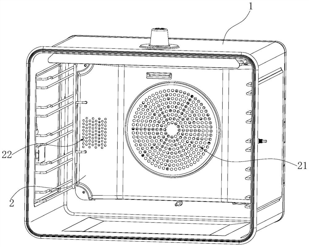
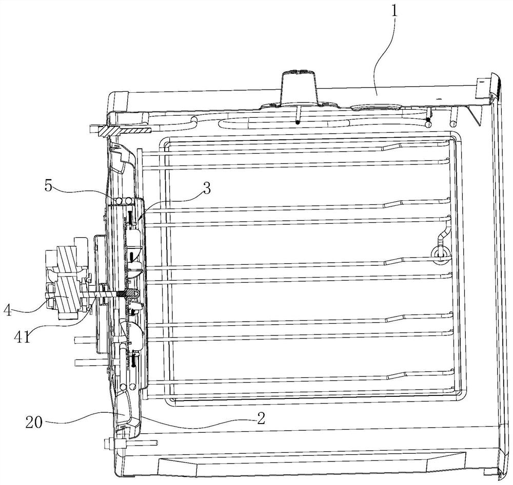
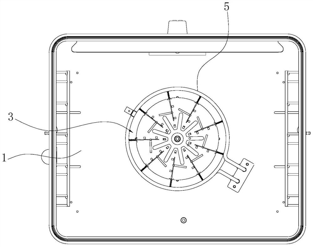
[0026] like Figure 1~6 As shown, an oven includes an inner container 1 and a fan blade structure 3. The rear side of the inner container 1 is vertically provided with a hot air baffle 2 with an air inlet 21 and an air outlet 22. The hot air baffle 2 and the inner container The backboard of 1 encloses the hot air chamber 20, and the rear surface of the backboard of the liner 1 is equipped with a hot air motor 4, and the motor shaft 41 of the hot air motor 4 penetrates in the above-mentioned hot air chamber 20 along the front and rear direction, and the above-mentioned fan blades The structure 3 is located in the hot air chamber 20 and installed on the motor shaft 41 of the hot air blower motor 4 , and the outer periphery of the fan blade structure 3 is provided with an annular heating pipe 5 .

[0027] The fan blade structure 3 includes a dis...


PUM


Abstract

The invention relates to a fan blade structure for cooking equipment and an oven, comprising a support plate, blades are arranged at intervals along the circumferential direction on the first plate surface of the support plate, each blade extends radially along the support plate and is perpendicular to the support plate The first disk surface of the plate also includes guide components and elastic tension, and the size of the elastic tension is proportional to the size of the rotating centrifugal force on the corresponding blade. Under the action of the resultant force of the rotating centrifugal force and the elastic pulling force, it moves radially between the minimum distance and the maximum distance from the center of the support plate, and when the resultant force of the rotating centrifugal force and the above elastic pulling force is 0, each blade at rest. The invention can change the area of ​​the low-pressure area of ​​the fan blade according to the speed of the fan blade, and then change the flow velocity of the airflow around the fan blade, thereby meeting the requirements for airflow temperature and flow velocity under different baking conditions, and improving the comprehensive baking of the oven performance.

Description

technical field [0001] The invention relates to the field of cooking equipment, in particular to a fan blade structure used for cooking equipment and an oven with the structure. Background technique [0002] Cooking equipment with baking functions such as electric ovens are generally provided with a hot air baffle on the rear side of the inner tank. The hot air baffle and the back plate of the inner tank form a hot air chamber. The outer periphery of the leaf is provided with a back heating pipe. In this way, when the oven is working, the fan blades rotate, and the cold air in the inner tank is sucked into the hot air chamber through the air inlet on the hot air baffle, and the hot air heated by the back heating tube passes through the hot air baffle under the centrifugal force of the fan blades. The air outlet of the plate is returned to the inner container for toasting the food in the inner container. [0003] The blades of the existing fan blades are generally of fixed ...

Claims


Application Information

Patent Timeline
Patent Type & Authority Patents(China)
IPC IPC(8): A47J37/06
CPCA47J37/0641A47J37/0664
Inventor 王丁谭万福姚青
Owner NINGBO FOTILE KITCHEN WARE CO LTD
Learn More