Silk conveying mechanism and thread cutting device

A wire feeding and along-the-line technology, which is applied in the field of wire cutting machines, can solve the problems of inconsistent pressing force and low cutting precision of the wire cutting device, and achieve the effect of quick operation

Pending Publication Date: 2020-09-01
上海康德莱医疗器械自动化研究所有限公司
View PDF0 Cites 0 Cited by
  • Summary
  • Abstract
  • Description
  • Claims
  • Application Information

AI Technical Summary

Problems solved by technology

[0005] Therefore, the technical problem to be solved by the present invention is to overcome the inconsistency of the pressing force on the multiple

Method used


Image

  • Silk conveying mechanism and thread cutting device
  • Silk conveying mechanism and thread cutting device
  • Silk conveying mechanism and thread cutting device

Examples


Embodiment 1

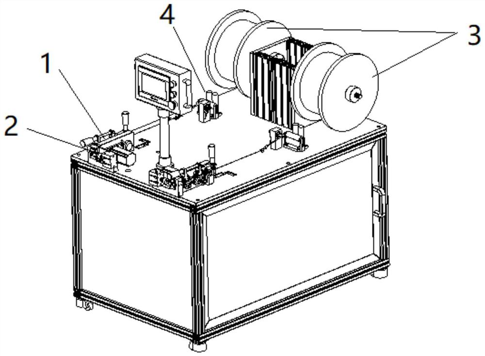
[0057] This embodiment provides a wire cutting device, such as figure 1 and figure 2 As shown, the thread cutting device includes a wire feeding mechanism 1 for conveying the wire and a thread cutting mechanism 2 for cutting the wire output from the output end of the wire feeding mechanism 1, wherein the thread cutting mechanism 2 is arranged on the wire feeding mechanism 1. At the outlet end 18 of the mechanism 1, the thread cutting mechanism 2 can be stably cut.

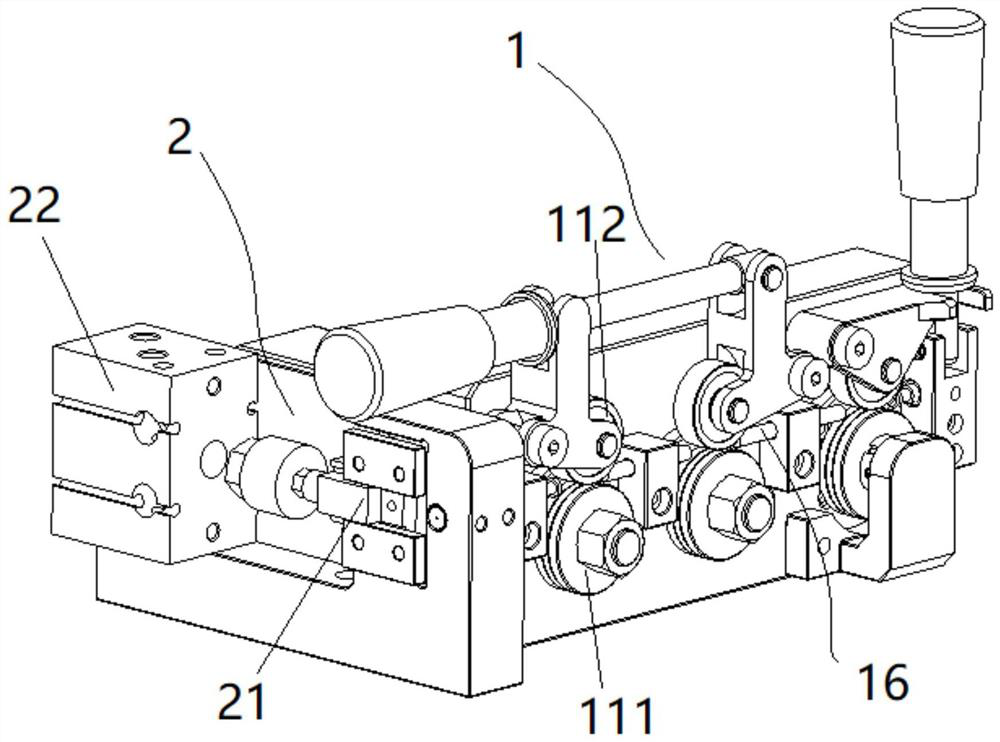
[0058] Specifically, see figure 2 and image 3 As shown, in the present embodiment, the above-mentioned thread cutting mechanism 2 includes a cutter 21 and a cutter driver 22 for driving the cutter 21 to move. The wire output from the wire outlet end 18 of the wire mechanism is cut. Specifically, the cutter driver can be driven by a cylinder or a motor.

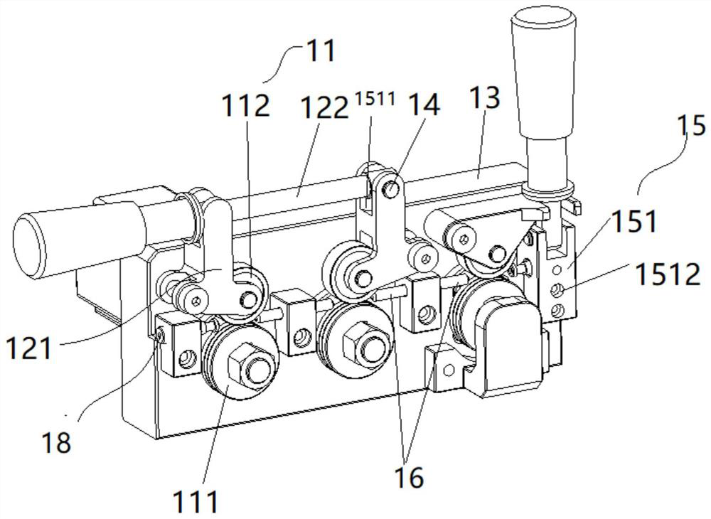
[0059] In this embodiment, the above-mentioned wire feeding mechanism 1 includes a mounting base 13, at least two conveying assemblies 11 and at least one a...

Embodiment 2

[0079] This embodiment provides a wire cutting device, see figure 2 , compared with the thread cutting device provided in Embodiment 1, the difference is that the structure of the adjustment member 121 is different. In this embodiment 1, the longitudinal section of the adjustment member 121 is set to be an inverted T shape, and the level of the T shape is Two ends of the vertical part are respectively connected to the first rotating shaft 14 and the pressing member 112 , and the end of the vertical part is connected to the first driving member 122 .

Embodiment 3

[0081] This embodiment provides a wire cutting device, see figure 2 , image 3 and Figure 8 The difference between this embodiment and Embodiment 1 and Embodiment 2 is that the support seat 151 in this embodiment can be directly installed on the above-mentioned installation seat 13, specifically, the support seat 151 can be provided with an installation hole 1512 , and arranged along the feeding direction of the wire, the above-mentioned limiting assembly 15 also includes fasteners, the support base 151 is installed on the support base 151 through fasteners, wherein the fasteners can pass through any one of the installation holes 1512, and then Fix the supporting base 151 on the mounting base 13, the mounting holes 1512 of this embodiment can be provided with at least two, such as three, four, and the specific number is arranged according to the actual situation. As the number increases, the supporting base The changeable position of 151 on the mounting base 13 will also i...


PUM


Abstract

The invention relates to the technical field of a thread cutting machine and particularly discloses a silk conveying mechanism and a thread cutting device. The silk conveying mechanism comprises at least two conveying assemblies and at least one adjusting assembly which are arranged on a mounting base; any one of the conveying assemblies comprises a driving piece and a pressing piece; the pressingpiece is driven by rotation of the driving piece to rotate; a thread passing channel is formed between the mutually pressed surfaces of the pressing piece and the driving piece; and the pressing piece in at least one conveying assembly is mounted on the adjusting assembly and is driven by the adjusting assembly to move to switch between the pressing state pressed on the corresponding driving piece and the loosening state of loosening the driving piece. The conveying assemblies and the adjusting assembly are arranged on the conveying path of the thread, so that the thread passing channel is formed between the driving piece; and the pressing force between the pressing piece and the driving piece is adjusted by the adjusting assembly, so that the pressing piece, and the pressing force of thesilk thread passing through the thread passing channel formed between the driving piece and the driving piece is adjusted.

Description

technical field [0001] The invention relates to the technical field of wire cutting machines, in particular to a wire feeding mechanism and a wire cutting device. Background technique [0002] At present, when the silk thread is cut to the required length, it is generally cut manually. The specific operation is: the silk thread is wound on the feeding roller, and the staff uses a fixed-length clamp to manually cut the thread. The pull-out end is continuously pulled forward and compared with the length of the fixture. When the length of the drawn thread is consistent with the length of the fixture, use a knife to cut the thread; then continue to pull the thread forward for the next match. The length of the jig is compared, and the cycle is repeated in this way to realize the cutting of the silk thread. However, the cutting method of this silk thread is inefficient, and when a large amount of cut silk thread is required, the manual method cannot meet the demand for material s...

Claims


Application Information

Patent Timeline
IPC IPC(8): B65H51/08B65H59/06B65H57/04B65H57/12B65H61/00B21F11/00B21F23/00
CPCB21F11/00B21F23/00B65H51/08B65H57/04B65H57/12B65H59/06B65H61/00B65H2701/35
Inventor 不公告发明人
Owner 上海康德莱医疗器械自动化研究所有限公司
Why Eureka
Try Eureka