Actuation and expansion device for automobile drum brake and drum brake

A drum brake and brake shoe technology, applied in the direction of brake parts, brake actuators, gear shifting mechanisms, etc., can solve the problems that the brake shoes cannot be braked synchronously, the braking distance is long, and the lift is small. Achieve the effect of favorable heat dissipation, large braking torque and alleviation of thermal recession

Inactive Publication Date: 2018-04-10
周广如
View PDF8 Cites 0 Cited by
  • Summary
  • Abstract
  • Description
  • Claims
  • Application Information

AI Technical Summary

Problems solved by technology

Although the brake with the above structure is simple in structure, it still has the following deficiencies because the center drive shaft is limited by its involute structure: 1. The lift of the center drive shaft is relatively too small when the center drive shaft rotates through the same angle
The amount of wear can only be compensated by frequently adjusting the rotation angle of the central drive shaft
2. The opening and returning of the brake shoe 3 is too slow, causing the brake to be delayed and the braking distance long, and the brake to be released incompletely, resulting in unnecessary friction
3. The involute curved surface of the central drive shaft is in line contact with the curved surface of the roller 15, which causes rapid wear and tear, resulting in increased opening and return resistance
4. Considering the relatively small lift of the center drive shaft, the gap between the friction plate 4 on the brake shoe 3 and the brake drum 1 can only be small
However, due to the asymmetric structure of the force points on the brake shoes, these two kinds of brakes cannot achieve the synchronous opening movement of the two brake shoes. Purpose, the other brake shoe cannot be contacted, and the purpose of braking cannot be achieved, that is, the two brake shoes cannot brake synchronously

Method used


Image

  • Actuation and expansion device for automobile drum brake and drum brake
  • Actuation and expansion device for automobile drum brake and drum brake
  • Actuation and expansion device for automobile drum brake and drum brake

Examples


Embodiment

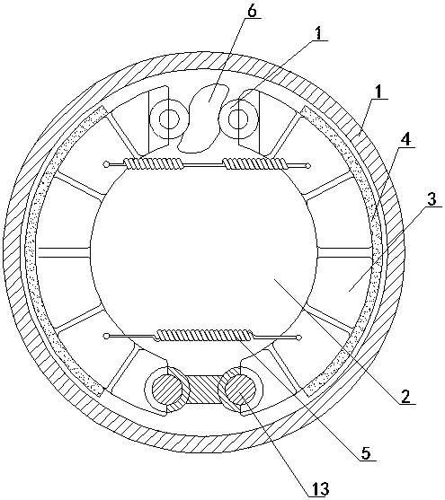
[0029] The drum brake of the present invention is mainly composed of a brake drum 1, a brake base plate 2, a brake shoe 3, a friction plate 4, a return spring 5 and an actuating opening device.

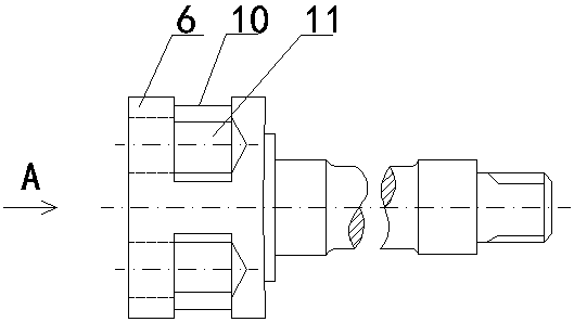
[0030] The brake drum 1 is slidingly connected with the axle of the automobile by means of rolling bearings, and the brake base plate 2 is fixedly connected with the axle of the automobile by means of connecting pieces. The lower ends of the two brake shoes 3 are respectively hinged with the brake bottom plate 2 through support pins 13 . Force-bearing arcuate surfaces 14 are respectively processed on the opposite surfaces of the top ends of the two brake shoes 3 . The axes of the two stressed arcuate surfaces 14 are on the same horizontal plane. Two friction discs 4 are respectively fixed on the outer arc surfaces of the two brake shoes 3 . The return spring 5 is fixedly connected between the two brake shoes 3 . The actuation and expansion device is arranged between the top ends of...


PUM


Abstract

The invention discloses an actuating expanding device for an automobile drum brake and the drum brake comprising the actuating expanding device, and belongs to the production field of brakes. The actuating expanding device is characterized in that two radial deep grooves which are symmetrically distributed are formed in the head end of a centre driving shaft, an axial concave arc face is formed in the bottom of each groove, a connecting rod is inserted and connected into each radial deep groove, the two ends of each connecting rod are both convex arc faces, one end of each connecting rod is in sliding fit with the corresponding axial concave arc face, the outer side of the head end of the center driving shaft is sleeved with a guiding part which is fixedly arranged, the two ends of the guiding part are respectively provided with a round guiding hole, a top rod in sliding fit with each round guiding hole is arranged in each round guiding hole, one end of each top rod is a concave arc face and in sliding fit with the convex arc faces at the outer ends of the connecting rods, and the other end of each top rod is convex arc face. A stress arc face is machined at the top end of a brake shoe of the brake and in sliding fit with the top rods. Compared with the prior art, the actuating expanding device is large in expanding angle and flexible in expanding and returning; the drum brake has the advantages of being stable in braking, short in braking distance and the like.

Description

technical field [0001] The invention relates to the field of brake production, in particular to an actuating opening device for an automobile drum brake and the drum brake. Background technique [0002] Most of the existing automobile drum brakes push the two rollers 15 on the two brake shoes 3 on both sides with the involute curved surface of the head end (or cam) of the central drive shaft 6, and then push the two brake shoes 3 to be wound. Two supporting pin shafts 13 on the movable base plate 8 rotate oppositely and spread outwards. The friction plate 4 installed on the outer arc surface of the brake shoe 3 is tightly pressed on the inner circular surface of the rotating brake drum 1, and the purpose of deceleration or parking of the car is achieved by friction. Central drive shaft 6 and roller 15 act as its actuation and expand device (as attached figure 1 shown). Although the brake with the above structure is simple in structure, it still has the following disadvant...

Claims


Application Information

Patent Timeline
Patent Type & Authority Patents(China)
IPC IPC(8): F16D65/14F16D65/08F16D121/14F16D125/68
Inventor 周广如
Owner 周广如
Why Eureka
Try Eureka