Package pressing conveying structure applicable to packaging machine

A packaging machine and conveying mechanism technology, applied in packaging, paper product packaging, transportation and packaging, etc., can solve the problems of low packing conveying efficiency, long conveying stroke and high maintenance cost, achieve high packing conveying efficiency and improve packaging. Efficiency and low maintenance costs

Active Publication Date: 2016-07-20
上海松川峰冠包装自动化有限公司
View PDF6 Cites 6 Cited by
  • Summary
  • Abstract
  • Description
  • Claims
  • Application Information

AI Technical Summary

Problems solved by technology

[0004] The prior art bale conveying structure adopts a two-stage conveying mechanism, in which the front end of the first conveying mechanism has an integrated baling head, and the first conveying mechanism will act together with the baling head while compressing the bales; The conveying mechanism of the first stage is shorter than the conveying mechanism of the second stage. In terms of power drive, this compressed bag conveying structure requires three power sources.
The three power sources respectively drive the packing head, the first conveying mechanism and the second conveying mechanism, with complex structure, high energy consumption and maintenance cost
[0006] The flattening bag pressing device disclosed in this patent document has a two-stage conveying structure for the bag pressing, and the bag pressing and the first stage of conveying are integrated structures, and the conveyor belt will nod along with the bag pressing, which affects the appearance of the bag pressing; The conveying stroke is long, if the bag is stuck during the first stage of conveying, it will affect the conveying of the second stage, not only the conveying efficiency of the compressed bag is low, but also requires more power sources, high energy consumption, complex structure and high maintenance cost

Method used


Image

  • Package pressing conveying structure applicable to packaging machine
  • Package pressing conveying structure applicable to packaging machine
  • Package pressing conveying structure applicable to packaging machine

Examples


Embodiment 1

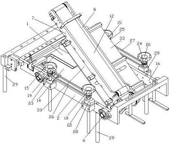
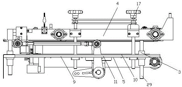
[0047] The compressed bag conveying structure suitable for packaging machines includes a pressed bag plate 1, a lifting gantry 2 and a conveying mechanism 3 driven by a power source. The conveying mechanism 3 is a one-piece structure, including an upper conveying part 4 and a lower conveying Part 5, the pressing plate 1 is arranged on the lifting gantry 2, one end of the upper conveying part 4 is hinged on the lifting gantry 2 through the hinge shaft 6, and the upper conveying part 4 is in contact with the pressing plate 1 , the upper conveying part 4 is located above the pressing plate 1 .

[0048] This embodiment is the most basic implementation. The conveying mechanism is a one-piece structure, including an upper conveying part and a lower conveying part. The pressing plate is arranged on the lifting gantry, and one end of the upper conveying part is hinged on the lifting gantry through a hinge shaft. , the upper conveying part is in contact with the pressing plate, and the...

Embodiment 2

[0050] The compressed bag conveying structure suitable for packaging machines includes a pressed bag plate 1, a lifting gantry 2 and a conveying mechanism 3 driven by a power source. The conveying mechanism 3 is a one-piece structure, including an upper conveying part 4 and a lower conveying Part 5, the pressing plate 1 is arranged on the lifting gantry 2, one end of the upper conveying part 4 is hinged on the lifting gantry 2 through the hinge shaft 6, and the upper conveying part 4 is in contact with the pressing plate 1 , the upper conveying part 4 is located above the pressing plate 1 .

[0051] The upper conveying part 4 comprises a first supporting frame 7 and a second supporting frame 8, and the lower conveying part 5 comprises a third supporting frame 9, a fourth supporting frame 10 and a support frame arranged on the third supporting frame 9 and the fourth supporting frame 10. The support plate 11 is located between the third support frame 9 and the fourth support fra...

Embodiment 3

[0054] The compressed bag conveying structure suitable for packaging machines includes a pressed bag plate 1, a lifting gantry 2 and a conveying mechanism 3 driven by a power source. The conveying mechanism 3 is a one-piece structure, including an upper conveying part 4 and a lower conveying Part 5, the pressing plate 1 is arranged on the lifting gantry 2, one end of the upper conveying part 4 is hinged on the lifting gantry 2 through the hinge shaft 6, and the upper conveying part 4 is in contact with the pressing plate 1 , the upper conveying part 4 is located above the pressing plate 1 .

[0055] The upper conveying part 4 includes a first support frame 7 and a second support frame 8 .

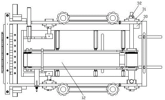
[0056] The upper conveying part 4 also includes an upper synchronous belt 12, and the upper synchronous belt 12 is arranged between the first supporting frame 7 and the second supporting frame 8, and the lower conveying part 5 includes a third supporting frame 9, a fourth supporting frame 1...


PUM


Abstract

The invention discloses a package pressing conveying structure applicable to a packaging machine and belongs to the technical field of packaging machines. The package pressing conveying structure applicable to the packaging machine comprises a package pressing plate and is characterized in that the package pressing conveying structure further comprises a lifting portal frame and a conveying mechanism driven by a power source; the conveying mechanism is of a one-segment type structure and comprises an upper conveying part and a lower conveying part; the package pressing plate is arranged on the lifting portal frame; one end of the upper conveying part is hinged to the lifting portal frame through a hinging shaft; the upper conveying part makes contact with the package pressing plate; and the upper conveying part is located on the package pressing plate. According to the package pressing conveying structure applicable to the packaging machine, the package pressing plate and the conveying mechanism are separated; during package pressing, the conveying mechanism cannot make downward-pressing swing action along with the package pressing plate, only when the conveying mechanism detects that materials come, can the conveying mechanism rotate, and therefore energy consumption is lower, and the conveying efficiency is higher; and the upper conveying part makes contact with the package pressing plate so that the materials pressed by the package pressing plate can be square, regular and attractive, the lower conveying part is used in cooperation so that material packages conveyed in a package pressing manner can be more orderly and compacted, and therefore the subsequent packaging efficiency can be improved.

Description

technical field [0001] The invention relates to the technical field of packaging machines, in particular to a compressed bag conveying structure suitable for packaging machines. Background technique [0002] The packaging machine replaces the traditional manual packaging and has the characteristics of fast speed and neat and beautiful packaging. The packaging materials of the packaging machine can be candies, biscuits, paper towels, etc. Among them, the paper towel packaging machine is mainly used for the bagging and packaging of various specifications of soft paper towels. The paper towel packaging machines can be divided into: roll paper packaging machines, paper towel packaging machines, three-dimensional paper towel packaging machines, and wallet paper towels. Packaging machines, etc. Paper pumping packaging machines can be divided into three types: reciprocating packaging machines, three-dimensional packaging machines, and rotary packaging machines. [0003] With the...

Claims


Application Information

Patent Timeline
IPC IPC(8): B65B61/24B65B25/14
CPCB65B25/14B65B61/24
Inventor 黄松彭衡湘
Owner 上海松川峰冠包装自动化有限公司
Why Eureka
Try Eureka