An oil leakage prevention valve for power transformer oil tank

A power transformer, oil leakage prevention technology, applied in the direction of lift valve, valve device, engine components, etc., can solve the problems of damp insulation oil, transformer coil deformation, friction and switching torque, etc., to improve sealing performance, reduce The effect of switching torque and reducing frictional resistance

Active Publication Date: 2017-01-04
STATE GRID CORP OF CHINA +1
View PDF5 Cites 0 Cited by
  • Summary
  • Abstract
  • Description
  • Claims
  • Application Information

AI Technical Summary

Problems solved by technology

When the transformer leaks oil, the oil can come out and the water can go in, which will lower the oil level in the transformer. When the oil level is too low, the transformer coil will expose the oil level. The main problem is that the insulating oil will be damp. The damp of the transformer coil will affect the overall insulation of the transformer; at the same time, the output of the transformer will be affected due to poor heat dissipation, and the life of the transformer will be affected when it is overheated; it will also increase the noise of the transformer, and the transformer may be damaged due to excessive electromotive force when a large short-circuit current impacts. coil deformation
The upper and lower contact surfaces of the butterfly plate of the traditional transformer butterfly valve are wide, resulting in relatively large friction force and switching torque when the valve is in use, so that the upper and lower sealing surfaces of the butterfly plate and the valve seat are always in a state of sealing and extrusion when the valve is in use. During long-term use, Due to being squeezed by force, the valve body is prone to permanent deformation. With the long-term aging of the sealing ring and valve seat, oil leakage is prone to occur on the upper and lower sealing surfaces of the butterfly valve disc.

Method used


Image

  • An oil leakage prevention valve for power transformer oil tank
  • An oil leakage prevention valve for power transformer oil tank

Examples


Embodiment 1

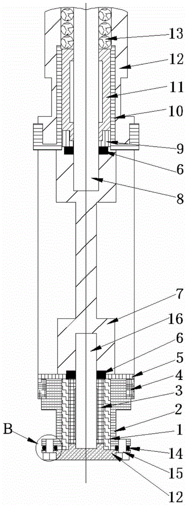
[0020] An anti-leakage valve for the oil tank of a power transformer, mainly composed of an upper valve stem 8, a butterfly plate 7, and a lower valve stem 16 connected in sequence, and flexible adjustment rings 6 are respectively fixed on the inner sides of the upper and lower ends of the butterfly plate 7, The outer side of the upper valve stem 8 is covered with an upper regulating bearing 11, the outer side of the lower valve stem 16 is covered with a lower regulating bearing 3, the outer casing of the upper regulating bearing 11 is equipped with an upper regulating ring 10, and the outer side of the lower regulating bearing 3 is covered by A lower adjustment ring 1 and an inner fastening ring 2 are sequentially set from inside to outside, the lower part of the inner fastening ring 2 is connected with the valve body 12 through bolts 15 , and the upper adjustment ring 10 is set in the valve body 12 . In order to better realize the present invention, a rigid adjustment ring 9 ...

Embodiment 2

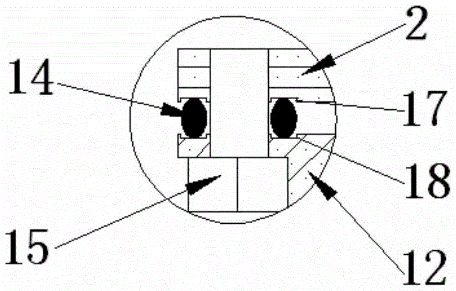
[0022] In order to better realize the present invention, on the basis of Embodiment 1, in this embodiment, a pad 5 is fitted outside the flexible adjustment ring 6 located at the lower end of the butterfly plate 7 . In order to better realize the present invention, an outer fastening ring 4 is fitted on the outer side of the cylindrical surface of the inner fastening ring 2 . In order to better realize the present invention, an upper groove 17 is provided on the surface where the inner fastening ring 2 is connected with the valve body 12 , and an O-ring 14 is fixed inside the upper groove 17 . The surface of the valve body 12 connected with the inner fastening ring 2 is provided with a lower groove 18 corresponding to the upper groove 17 . After the flexible adjusting ring 6 is set on the lower end of the butterfly plate 7 for sealing, the gasket 5 is placed outside the flexible adjusting ring to further seal the lower end of the butterfly plate 7 and effectively prevent oil l...


PUM


Abstract

The invention discloses an anti-oil-leakage valve used for a power transformer oil tank. The anti-oil-leakage valve mainly comprises an upper valve rod, a butterfly plate and a lower valve rod, wherein the upper valve rod, the butterfly plate and the lower valve rod are sequentially connected. Flexible adjustment rings are fixed to the inner side of the upper end surface of the butterfly plate and the inner side of the lower end surface of the butterfly plate respectively, the upper valve rod is sleeved with an upper adjustment bearing, the lower valve rod is sleeved with a lower adjustment bearing, the upper adjustment bearing is sleeved with an upper adjustment ring, the lower adjustment bearing is sleeved with a lower adjustment ring and an inner tightening ring from inside to outside in sequence, the lower portion of the inner tightening ring is connected with a valve body through a bolt, and the valve body is sleeved with the upper adjustment ring. According to the anti-oil-leakage valve used for the power transformer oil tank, because the upper adjustment bearing and the lower adjustment bearing are adopted, friction resistance applied to the valve rods can be reduced, sealing conditions of the upper and lower end surfaces of the butterfly plate can be easily changed, and the sealing performance of the valve is improved. An O-shaped ring is installed in the inner tightening ring in the form of a groove, and therefore the opening or closing torque of the valve can be reduced; because the flexible adjustment rings and rigid adjustment rings are arranged on the upper end surface of the butterfly plate as well as the lower end surface of the butterfly plate, the opening or closing torque can be reduced, deformation is avoided, and a good oil leakage preventing effect is achieved.

Description

technical field [0001] The invention relates to the field of power transformer equipment, in particular to an oil leakage prevention valve used in a power transformer oil tank. Background technique [0002] Transformer leakage can be roughly divided into sealing leakage and welding leakage. When the transformer leaks oil, the oil can come out and the water can go in, which will lower the oil level in the transformer. When the oil level is too low, the transformer coil will expose the oil level. The main problem is that the insulating oil will be damp. The damp of the transformer coil will affect the overall insulation of the transformer; at the same time, the output of the transformer will be affected due to poor heat dissipation, and the life of the transformer will be affected when it is overheated; it will also increase the noise of the transformer, and the transformer may be damaged due to excessive electromotive force when a large short-circuit current impacts. The coi...

Claims


Application Information

Patent Timeline
Patent Type & Authority Patents(China)
IPC IPC(8): F16K1/226F16K1/46F16K1/32
CPCF16K1/221F16K1/224F16K1/2261F16K1/2263
Inventor 谢光彬
Owner STATE GRID CORP OF CHINA
Why Eureka
Try Eureka