
Air cooling device

An air cooling and cooler core technology, which is applied in household refrigeration devices, lighting and heating equipment, household appliances, etc., can solve the problems of affecting the service life of the equipment, the weight of the cooler core, and the inconvenience of installation and adjustment

Active Publication Date: 2014-07-02
YANCHENG INST OF TECH
View PDF8 Cites 2 Cited by
  • Summary
  • Abstract
  • Description
  • Claims
  • Application Information

AI Technical Summary

Problems solved by technology

[0003] (1) The upper part of the pushed-in cooler core cannot be completely sealed, and even if the welding quality is fine, its parallelism requirements cannot be guaranteed. The gasket is also placed together when the cooler core is pushed in, and it is easy to fall off and break without pressing. device, hot air flows through the contact surface gap at high speed, but cannot completely pass through the cooler core, affecting its cooling effect
[0004] (2) Most of the cooler cores are made of copper tubes and copper sheets, which are large in size and weight. The volume generally exceeds 1000*600*400mm3, and the weight is over 950kg. Due to the restrictions of self-weight and installation ports during installation, it is easy to Inclined, long installation time, difficult to adjust
[0005] (3) The cylinder is designed as an integrated structure, which is not conducive to the internal structure of the cylinder and the installation and maintenance of the cooler core
[0006] (4) The cylinder has a circular structure, the cooler core is square, and the cooler core is installed horizontally inside the cylinder. The gap between the heat sink and the cylinder wall is relatively large, and some hot air passes through the gap without being fully heated with the coolant. Exchange, low cooling efficiency
[0007] (5) The commonly used cooler core weighs more than 950 kg. It is in a suspended state without support in the cylinder. It is prone to deformation under the action of its own weight and air pressure, which may damage the cylinder and affect the service life of the equipment.
[0008] (6) Due to the heavy weight of the cooler core, it is extremely inconvenient to install and adjust

Method used


Image

  • Air cooling device
  • Air cooling device

Examples


Embodiment Construction

[0024] Embodiments of the invention are described in detail below, but the invention can be practiced in many different ways as defined and covered by the claims.

[0025] High-pressure air cooling technology is an important cooling technology in the fields of electric power, petroleum industry and customs. Usually, the air cooling device is a vertical cylinder structure, and the cooler core is inserted and installed in the middle of the cylinder horizontally. Water) contacts heat exchange, and the cooled air is discharged from the outlet at the bottom of the cylinder.

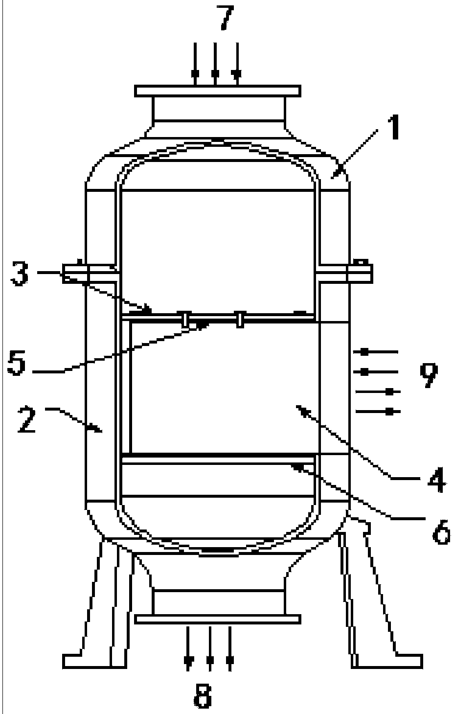
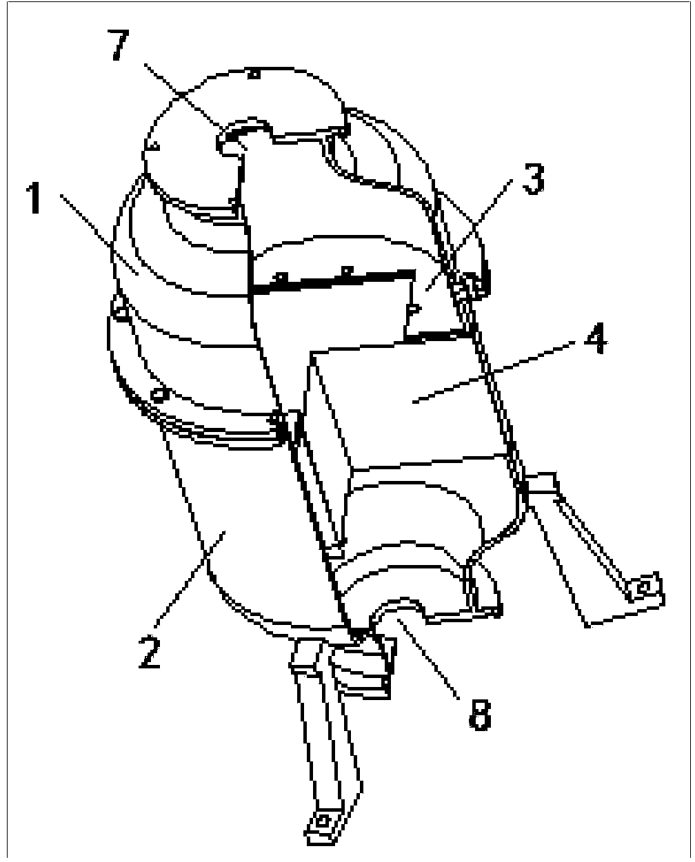
[0026] In order to solve the technical problems in the prior art, please refer to Figure 1 to Figure 2 , the present invention provides an air cooling device, comprising: an upper cylinder body 1; a lower cylinder body 2 connected to the lower cylinder body 2, an accommodation cavity is formed between the lower cylinder body 2 and the lower cylinder body 2; a first sealing steel plate 3 , installed in the h...


PUM


Abstract

The invention relates to an air cooling device. The air cooling device comprises an upper barrel, a lower barrel, a first sealing steel plate and a cooler core, wherein the upper barrel is connected with the lower barrel; an accommodating cavity is formed between the upper barrel and the lower barrel; the first sealing steel plate is arranged in the accommodating cavity; the outer edge of the first sealing steel plate is hermetically connected with the inner wall of the lower barrel; an opening is formed in the first sealing steel plate; the cooler core is arranged below the first sealing steel plate and is positioned in the accommodating cavity; the sizes and the positions of radiating fins of the cooler core are matched with the size and the position of the opening in the first sealing steel plate; and the cooler core is hermetically connected with the first sealing steel plate. Because the outer edge of the first sealing steel plate is hermetically connected with the inner wall of the lower barrel, hot air entering the air cooling device enters the cooler core from the opening in the first sealing steel plate. The square air inlet of the cooler core and a circular gap between the upper barrel and the lower barrel can be sealed by using the first sealing steel plate; and the cooling efficiency is improved.

Description

technical field [0001] The invention relates to the field of air cooling equipment, in particular to an air cooling device. Background technique [0002] The air cooler in the prior art has an integral cylindrical structure, high-pressure air enters from the top and exits from the bottom, and the middle part of the core of the cooler is inserted and installed horizontally. Such air coolers have the following disadvantages: [0003] (1) The upper part of the pushed-in cooler core cannot be completely sealed, and even if the welding quality is fine, its parallelism requirements cannot be guaranteed. The gasket is also placed together when the cooler core is pushed in, and it is easy to fall off and break without pressing. device, the hot air flows through the contact surface gap at high speed, but cannot completely pass through the cooler core, which affects its cooling effect. [0004] (2) Most of the cooler cores are made of copper tubes and copper sheets, which are large ...

Claims


Application Information

Patent Timeline
IPC IPC(8): F25D1/02
Inventor 许宁许玥晏云飞侯贵华姜瑞雨张峰
Owner YANCHENG INST OF TECH
Learn More