Heating stove

A technology for heating furnaces and furnace shells, applied in the field of heating devices, can solve problems such as inability to ensure full combustion of coal, inability to fully utilize heat energy, waste of national energy, etc., and achieve the effects of strong firepower, wide application range, and reduced fuel use

Pending Publication Date: 2021-06-18
曹同良
View PDF0 Cites 0 Cited by
  • Summary
  • Abstract
  • Description
  • Claims
  • Application Information

AI Technical Summary

Problems solved by technology

At present, the primary heater of the commonly used coal-fired stove has too thick inner wall of the furnace, most of which are between 40-90mm, and its heat conduction effect is too poor to fully transfer the heat generated by the coal to the circulating water on the outer wall of the furnace. Its heat conduction efficiency is about 30-50%, and the inner wall of the furnace has the best effect within 25mm. However, due to the rapid heat dissipation, the water jacket furnace wall cools down too quickly, and the water directly wraps the furnace, resulting in low fire. Lower furnace temperature is a disadvantage of heating furnaces currently on the market, resulting in insufficient use of heat energy and low thermal efficiency. Due to defective product design and waste of national energy, our reverse circulation and reverse burning constant temperature heating furnace solves the above problems They have these defects (positive circulating hot water is on top, cold water is on the bottom, and the cold water below just wraps the combustion chamber, and because the external water temperature is low, it cannot guarantee the full combustion of coal), this patent reverse circulation and anti-burning constant temperature heating furnace just solves the above In addition, we set a flue gas retaining ring above the furnace mouth to force the direction of the smoke to be changed, so that the heat that cannot be absorbed in the furnace can be fully absorbed twice, and the thermal efficiency of coal has increased by about 95%.

Method used


Image

  • Heating stove
  • Heating stove
  • Heating stove

Examples


Embodiment Construction

[0027] A heating furnace of the present invention will be further described in detail below in conjunction with the accompanying drawings.

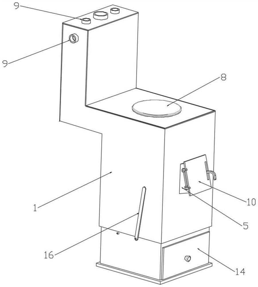
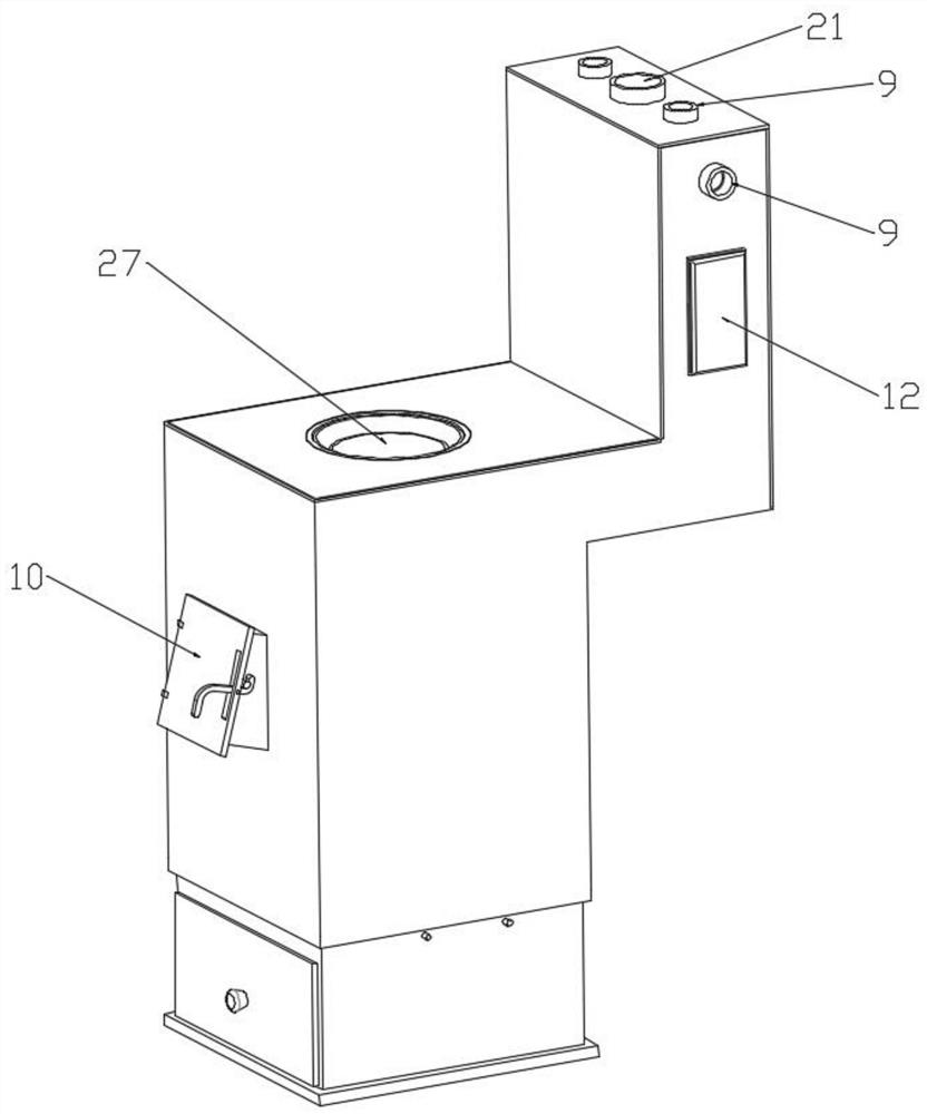
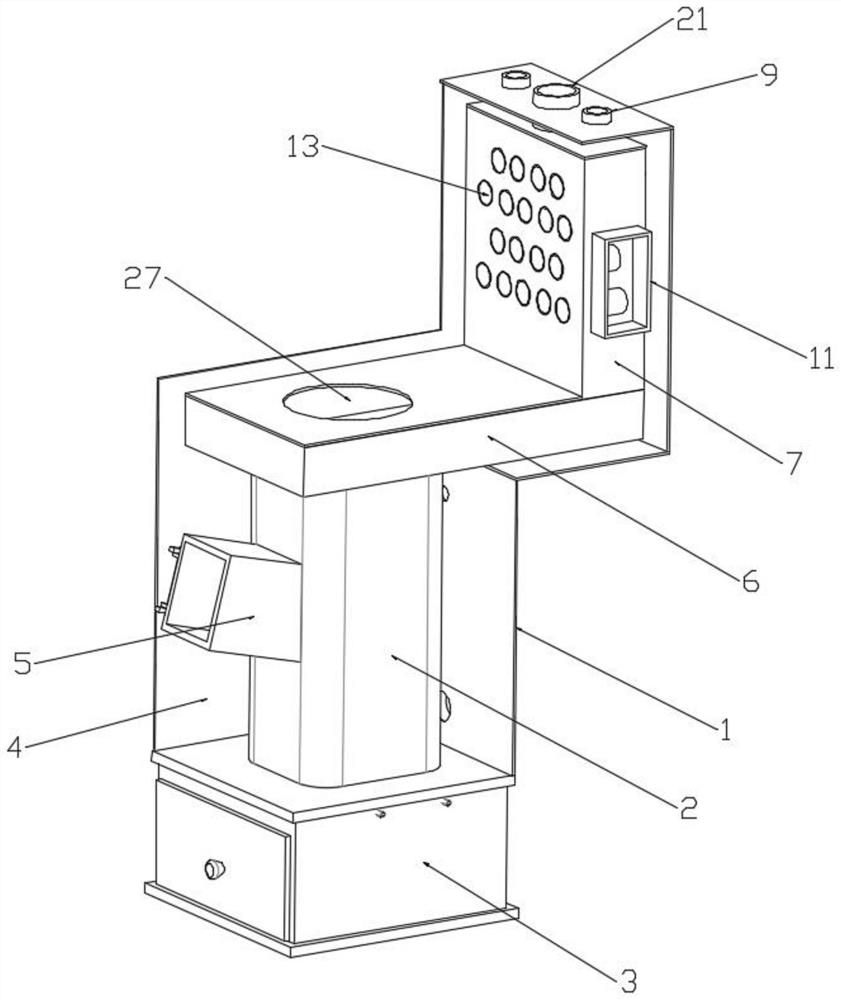
[0028] combined with Figure 1-Figure 7 , a heating furnace, comprising a base 3 and a combustion chamber 2 arranged on the upper part of the base 3, the upper part of the combustion chamber 2 is provided with a horizontal flue 6, and the end of the horizontal flue 6 away from the combustion chamber 2 is connected with a vertical flue 7. The combustion chamber 2, the horizontal flue 6 and the vertical flue 7 are covered with a furnace shell 1, and the inner wall of the furnace shell 1 is closed with the outer wall of the combustion chamber 2, the horizontal flue 6 and the vertical flue 7 The body is the water chamber 4, the top plate of the horizontal flue 6 is located directly above the outlet of the combustion chamber 2, and a furnace mouth 27 is provided, and a flue gas retaining ring 22 is arranged between the outlet of the combustion...


PUM


Abstract

The invention relates to the field of heating devices, in particular to a heating stove which comprises a base and a combustion chamber arranged on the upper portion of the base. A horizontal flue is arranged on the upper portion of the combustion chamber, a vertical flue is connected to the end, away from the combustion chamber, of the horizontal flue, and a stove shell is arranged outside the combustion chamber, the horizontal flue and the vertical flue in a wrapping mode; a closed cavity between the inner wall of the stove shell and the outer walls of the combustion chamber, the horizontal flue and the vertical flue is a water chamber, a stove opening is formed in the position, over an outlet of the combustion chamber, of an upper top plate of the horizontal flue, a smoke check ring is arranged between the outlet of the combustion chamber and the stove opening, a smoke outlet is formed in the side, away from the vertical flue, of the upper portion of the ring body of the smoke check ring, a water outlet pipe is arranged at the bottom of the stove shell, and a water inlet pipe is arranged at the top of the stove shell; and a layer of refractory material is attached to the inner wall of the combustion chamber, a grate bridge is arranged at the bottom of the combustion chamber, and a supporting plate used for supporting the refractory material is arranged below the combustion chamber.

Description

technical field [0001] The invention relates to the field of heating devices, in particular to a heating furnace. Background technique [0002] Most of the vast northern rural families use coal-fired water heating stoves for heating in winter. With the improvement of living standards, people have higher and higher requirements for coal-fired water heating stoves, that is, they should seek a safe coal-saving, non-polluting thermal efficiency High, convenient stoves for family use, meeting the needs of the current private plumbing coal-fired stove market. At present, the primary heater of the commonly used coal-fired stove has too thick inner wall of the furnace, most of which are between 40-90mm, and its heat conduction effect is too poor to fully transfer the heat generated by the coal to the circulating water on the outer wall of the furnace. Its heat conduction efficiency is about 30-50%, and the inner wall of the furnace has the best effect within 25mm. However, due to t...

Claims


Application Information

Patent Timeline
Patent Type & Authority Applications(China)
IPC IPC(8): F24D15/02F23J11/00F23J15/06F23J1/00F24B7/00F24B13/00
CPCF23J1/00F23J11/00F23J15/06F24B7/005F24B13/008F24D15/02
Inventor 曹同良
Owner 曹同良
Why Eureka
Try Eureka