Inflaming retarding type anti-explosion valve

A technology for explosion-proof valves and valve seats, which is applied in the direction of engine components, machines/engines, mechanical equipment, etc., and can solve problems such as deformation of flame retardant sheets or flame retardants, pressure increase, and accumulation of local channel airflow, so as to increase distance and Time, stress reduction, release stress reduction effect

Active Publication Date: 2017-12-22
ZHEJIANG UNIV OF TECH
View PDF7 Cites 0 Cited by
  • Summary
  • Abstract
  • Description
  • Claims
  • Application Information

AI Technical Summary

Problems solved by technology

The upper and lower penetration of the flame retardant sheet will easily cause high temperature and high pressure airflow to the upper part of the explosion-proof valve, resulting in excessive load on the upper part of the explosion-proof valve, which is not conducive to pressure reduction and flame extinguishing
The flame retardant sheet is perpendicular to the valve seat and arranged radially along the annular cavity. Once the height of the flame retardant sheet is too high or the installation is not firm enough, when the high-pressure airflow hits the flame retardant sheet, it is easy to cause deformation of the flame retardant sheet or the flame retardant
The concave and convex points on the flame retardant sheet, because there is no clear staggered arrangement, easily cause the airflow to flow to the closer channel, resulting in the accumulation of airflow and pressure increase in the local channel

Method used


Image

  • Inflaming retarding type anti-explosion valve
  • Inflaming retarding type anti-explosion valve
  • Inflaming retarding type anti-explosion valve

Examples


Embodiment Construction

[0027] The present invention will be further described below in conjunction with the accompanying drawings.

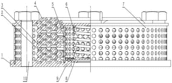
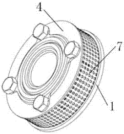
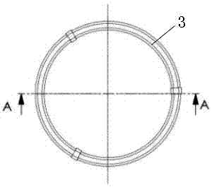
[0028] Such as Figure 1-12 As shown, a flame-retardant explosion-proof valve includes a valve seat 1, a cutoff plate 2, a flame-retardant ring 3, a valve cover 4, an inner guide ring 5, a spring 6, an outer guide ring 7, a valve disc 8, a seal Ring 9 and bolt 10. The valve cover 4 is fixed on the valve seat 1, and a flame retardant device is provided between the valve seat 1 and the valve cover 4. The flame retardant device includes an inner guide ring 5 provided inside the valve seat 1 and a The surfaces of the outer guide ring 7, the inner guide ring 5 and the outer guide ring 7 are respectively provided with guide holes; a group of flame-retardant rings 3 are arranged between the inner guide ring 5 and the outer guide ring 7, and the flame-retardant ring 3 A convex shoulder is evenly arranged along the circumferential direction, and the convex shoulder adopts a s...


PUM


Abstract

The invention discloses an inflaming retarding type anti-explosion valve. The inflaming retarding type anti-explosion valve comprises a valve seat and a valve cover which is fixedly arranged on the valve seat. An inflaming retarding device is arranged between the valve seat and the valve cover. The inflaming retarding device comprises an inner flow guiding ring which is arranged inside the valve seat and an outer flow guiding ring which is arranged on the edge of the valve seat, and the surface of the inner flow guiding ring and the surface of the outer flow guiding ring are each provided with guide holes. A set of inflaming retarding rings are arranged between the inner flow guiding ring and the outer flow guiding ring. The bottom of the valve seat is provided with a valve clack, the valve clack is provided with a spring, one end of the spring presses the valve clack tightly, and the other end of the spring abuts against the valve cover. The inflaming retarding type anti-explosion valve has the beneficial effects that the anti-explosion valve can increase the paths through which gas flow and flame pass and prolong the time when the gas flow and the flame pass through multiple times of diversion, extruding and other repeating process on concentrated gas flow, meanwhile, the gas flow makes sufficient contact and exchange heat with all ring faces of the inflaming retarding rings, finally, the pressure is reduced and released, the gas flow temperature is reduced, and the flame is completely extinguished.

Description

technical field [0001] The invention relates to the technical field of explosion-proof valves, in particular to a flame-retardant explosion-proof valve. Background technique [0002] When the oil mist mixture in the crankcase of the internal combustion engine reaches a certain concentration and the temperature reaches the temperature to detonate the oil mist mixture, high-pressure gas and high-temperature flame will be generated. When the pressure in the crankcase is higher than the rated pressure, the explosion-proof valve opens quickly, and the high-pressure gas and high-temperature flame pass through the explosion-proof valve to reduce the pressure, release the pressure, lower the temperature, and extinguish the flame. When the pressure in the crankcase is lower than the rated pressure, the explosion-proof valve is quickly closed to keep it in a sealed state, so as to prevent external fresh air from filling the crankcase and mixing with high-temperature oil mist to cause ...

Claims


Application Information

Patent Timeline
Patent Type & Authority Applications(China)
IPC IPC(8): F02B77/10
Inventor 刘红游国乔沈施佳沈少祥闫凡
Owner ZHEJIANG UNIV OF TECH
Why Eureka
Try Eureka