Electric connector
An electrical connector, a technology of one side, applied in the direction of connection, two-part connection device, parts of the connection device, etc., can solve the problems of increased volume, user inconvenience, cost increase, etc., to reduce the contact resistance value and improve the manufacturing process Simplicity and the effect of reducing production costs
- Summary
- Abstract
- Description
- Claims
- Application Information
AI Technical Summary
Problems solved by technology
Method used
Image

Examples
Embodiment 1
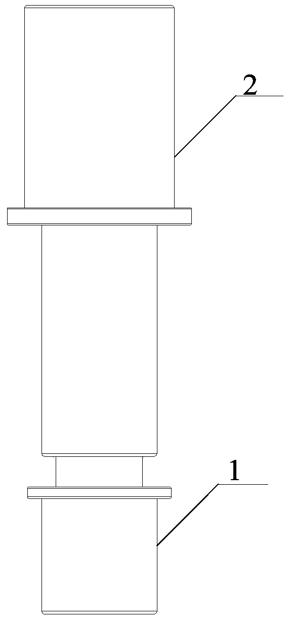
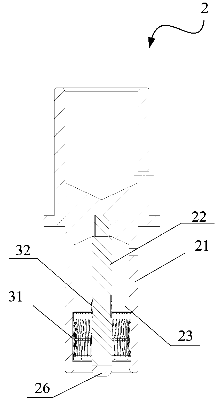
[0042] This embodiment discloses an electrical connector, which includes a plug 1 and a socket 2, wherein the socket 2 is composed of a main body 21 and a guide post 22, the main body 21 is provided with a jack 23 inside, the guide post 22 is located in the jack 23 and connected to the bottom of the main body 21;
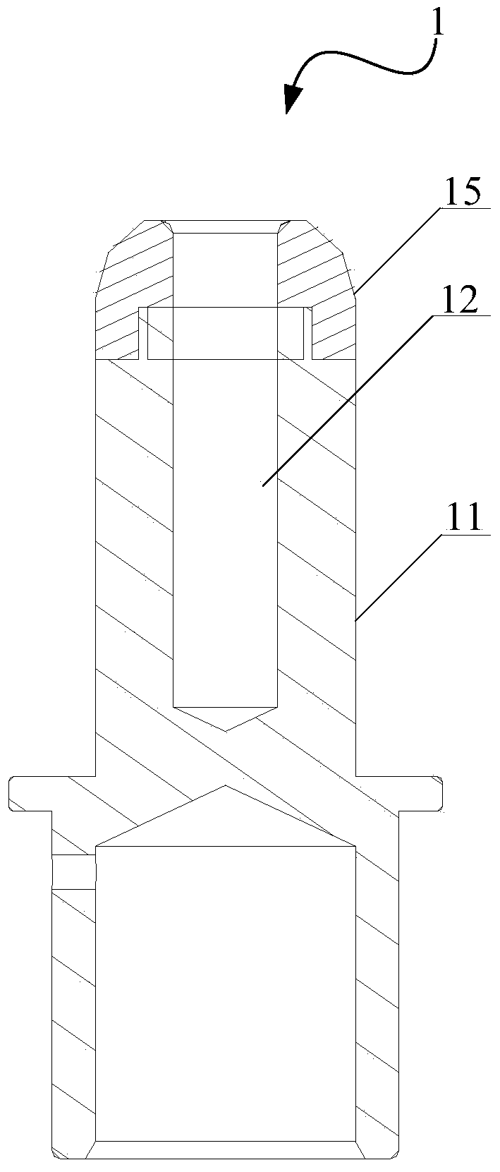
[0043]The plug 1 includes a plug main body 11 that cooperates with the jack 23, and a guide post groove 12 that cooperates with the guide post 22. When the plug and the socket are mated with each other, the plug main body 11 can be inserted into the jack 23, and the guide post 22 It is also adapted to be inserted into the guide post groove 12;
[0044] Either one of the outer peripheral surface of the socket 23 and the plug body 11 is provided with a first elastic member 31 protruding toward the other side, and any one of the guide post 22 and the guide post groove 12 is provided with a second elastic member 31 protruding toward the other side. elastic member 32 . ...
Embodiment 2
[0048] see Figure 5 , in this embodiment, we set the first elastic component 31 on the socket 23, and the first elastic component 31 is a crown spring-shaped elastic ring; the second elastic component 32 is set on the guide post 22, and the second elastic component 32 is a drum spring-shaped shrapnel circle.
[0049] Specifically, we can provide a first limiting groove 24 on the insertion hole 23 , and the first limiting groove 24 is used to clamp the first elastic member 31 (in this embodiment, it is a crown spring-shaped elastic ring). At the same time, a second limiting groove 25 is provided on the guide post 22 at the part that is in contact with the guide post groove 12 of the plug 1, and the second limiting groove 25 is used to clamp the second elastic member 32 (in this embodiment It is the drum spring-shaped shrapnel circle).
[0050] It should be noted that the first limiting groove 24 and the second limiting groove 25 are not limited to be on the same level, and t...
Embodiment 3
[0053] see Figure 6 , in this embodiment, we set the first elastic member 31 on the socket 23, and the first elastic member 31 is a crown spring-shaped elastic ring; the second elastic member 32 is arranged on the guide post groove 12, and the second The elastic component 32 is a crown spring-shaped elastic ring.
[0054] Specifically, we can provide a first limiting groove 24 on the insertion hole 23 , and the first limiting groove 24 is used to clamp the first elastic member 31 (in this embodiment, it is a crown spring-shaped elastic ring). At the same time, on the guide post groove 12, a second limiting groove 13 is provided on the part that is in contact with the guide post 22, and the second limiting groove 13 is used to clamp the second elastic member 32 (in this embodiment, it is the crown). reed coil).
[0055] It should be noted that the first limiting groove 24 and the second limiting groove 13 are not limited to be on the same level, and they may be staggered fro...
PUM
 Abstract
Description
Claims
Application Information
 - R&D
- Intellectual Property
- Life Sciences
- Materials
- Tech Scout
- Unparalleled Data Quality
- Higher Quality Content
- 60% Fewer Hallucinations
Browse by: Latest US Patents, China's latest patents, Technical Efficacy Thesaurus, Application Domain, Technology Topic, Popular Technical Reports.
© 2025 PatSnap. All rights reserved.Legal|Privacy policy|Modern Slavery Act Transparency Statement|Sitemap|About US| Contact US: help@patsnap.com