Battery unit, terminal equipment and battery unit configuration method

A battery unit and terminal equipment technology, applied in the electronic field, can solve the problems of short standby time and low energy storage utilization rate of mobile phones

Active Publication Date: 2014-07-02
LENOVO (BEIJING) CO LTD
View PDF5 Cites 8 Cited by
  • Summary
  • Abstract
  • Description
  • Claims
  • Application Information

AI Technical Summary

Problems solved by technology

Therefore, the utilization rate of energy storage in the batter

Method used


Image

  • Battery unit, terminal equipment and battery unit configuration method
  • Battery unit, terminal equipment and battery unit configuration method
  • Battery unit, terminal equipment and battery unit configuration method

Examples


Embodiment Construction

[0033] The following will clearly and completely describe the technical solutions in the embodiments of the present invention with reference to the accompanying drawings in the embodiments of the present invention. Obviously, the described embodiments are only some, not all, embodiments of the present invention. Based on the embodiments of the present invention, all other embodiments obtained by persons of ordinary skill in the art without making creative efforts belong to the protection scope of the present invention.

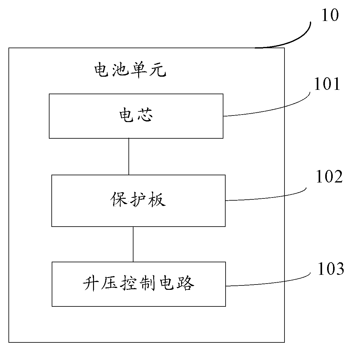
[0034] The embodiment of the present invention provides a battery unit 10, such as figure 1 As shown, the battery unit 10 includes:

[0035] The battery cell 101, the battery cell 101 is used for storing electric energy.

[0036] A protection plate 102 , the protection plate 102 is electrically connected to the battery cell 101 , and is used to provide overvoltage, overcurrent, overdischarge and overtemperature protection functions for the battery cell 101 du...


PUM


Abstract

The embodiment of the invention provides a battery unit, a piece of terminal equipment and a battery unit configuration method, and relates to the technical field of electronics. The utilization rate of stored energy in the battery unit can be improved. The battery unit comprises a battery cell used for storing electric energy, a protective plate electrically connected with the battery cell and used for providing over-voltage, over-current, over-discharge and over-temperature protection for the battery cell in the process of charge and discharge, and a boost control circuit electrically connected with the battery cell and used for boosting the output voltage of the battery cell when the output voltage of the battery unit is lower than or equal to a predetermined voltage. According to the battery unit, the terminal equipment and the battery unit configuration method provided by the embodiment of the invention, the battery unit and the battery unit configuration method are used in the terminal equipment with a battery unit.

Description

technical field [0001] The present invention relates to the field of electronic technology, in particular to a battery unit, a terminal device and a battery unit configuration method. Background technique [0002] In the prior art, mobile phones generally use a single battery unit for power supply, and the battery unit is usually obtained by packaging a battery cell and a protective plate. The battery cell is used to store electric energy, and the protection board is used to protect the battery cell in terms of voltage, current, temperature, etc. during the charging and discharging process of the battery cell. Generally, the working voltage range of the battery cell is 3.0V-4.2V, that is, the voltage of the battery cell is 4.2V when it is fully charged, and the voltage when the power supply is stopped is 3.0V in theory. [0003] Since the operating voltage of other circuits in the mobile phone is required to be greater than 3.0V, the predetermined voltage monitored by the p...

Claims


Application Information

Patent Timeline
IPC IPC(8): H02J7/00H04M1/02
Inventor 马超
Owner LENOVO (BEIJING) CO LTD
Why Eureka
Try Eureka