
Pressure dragging layering fracturing device

A technology of layered fracturing and dragging under pressure, which is applied in the direction of production fluid, wellbore/well components, earthwork drilling and production, etc. It can solve the problems of difficult positioning of downhole tools, long construction period, and inability to rotate, etc., to reduce The effect of reducing the risk of string jamming, shortening the construction period, and reducing equipment costs

Active Publication Date: 2014-07-09
BC P INC CHINA NAT PETROLEUM CORP +1
View PDF7 Cites 7 Cited by
  • Summary
  • Abstract
  • Description
  • Claims
  • Application Information

AI Technical Summary

Problems solved by technology

Coiled tubing bottom belt packer sandblasting and perforating layered fracturing device can realize dragging the pipe string under pressure, which has the advantages of fast layer change and short construction period, but it has high construction cost and difficulty in precise positioning of downhole tools (for Thin layers cannot be accurately positioned), low tensile load of tubing, and inability to rotate; conventional tubing bottom belt packer sandblasting perforation layered fracturing device has the advantages of low cost and unlimited number of fracturing layers, but After fracturing each layer, it is necessary to discharge fluid, backwash the well, and disassemble the wellhead. There are disadvantages that sand is easy to be stuck during the blowout process, and the labor intensity of frequent disassembly and assembly of the wellhead is high, and the construction period is long.

Method used


Image

  • Pressure dragging layering fracturing device

Examples


Embodiment Construction

[0012] Below in conjunction with accompanying drawing and specific embodiment the present invention is described in further detail:

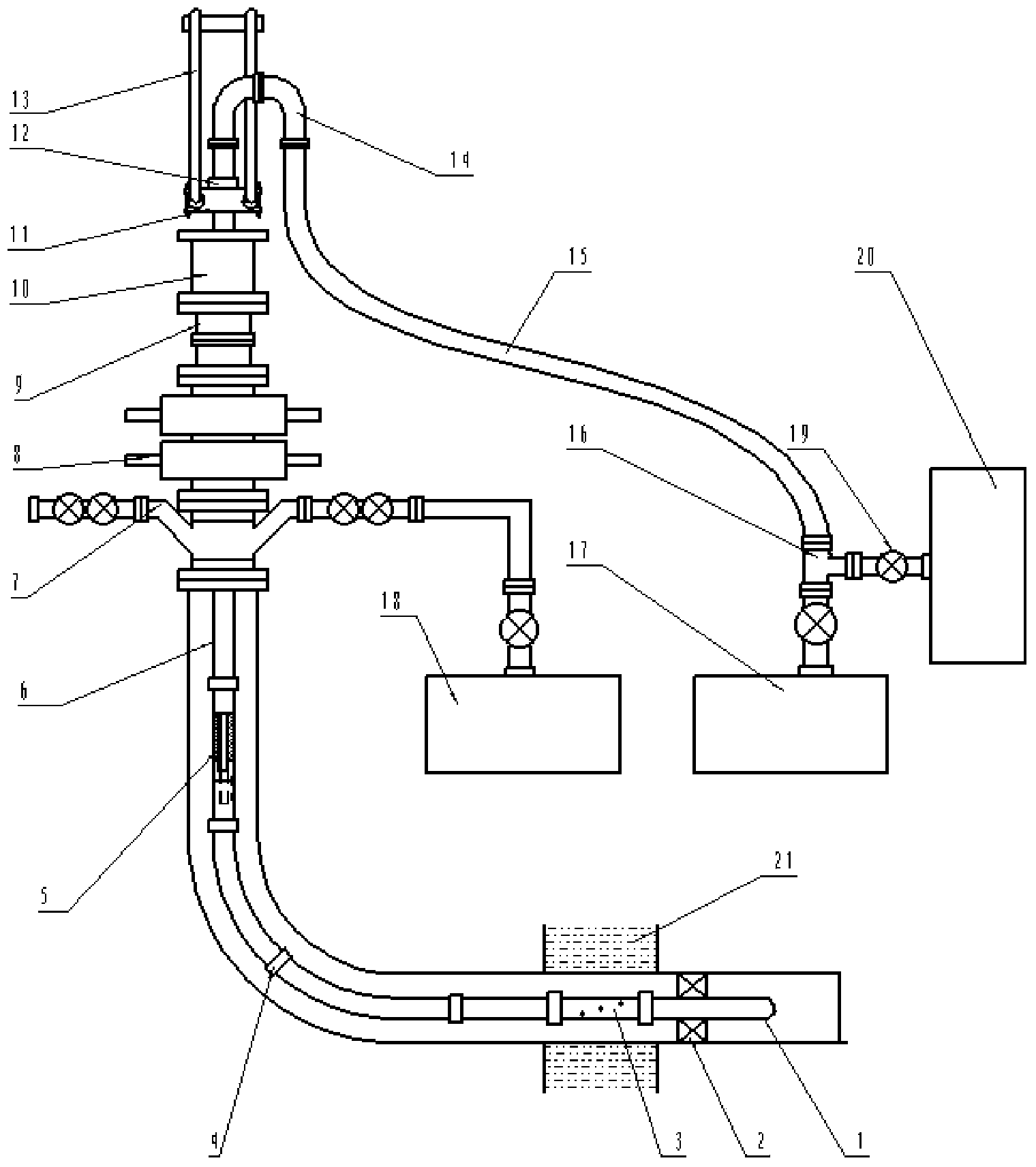
[0013] Such as figure 1 As shown, the pressure-dragging layered fracturing device of the present invention includes surface equipment and downhole tool strings, and the downhole tool strings include a cone plug 1, a packer 2, a hydraulic spray gun 3, a coupling tubing 4, Abrasion-resistant check valve 5, uncoupling tubing 6; surface equipment includes wellhead cross 7 corresponding to the pressure level during fracturing, on which double ram blowout preventer 8 is installed, and on double sluice The plate blowout preventer 8 is connected with the blowout preventer 9, and the blowout preventer 9 is connected with the anti-top pneumatic slip 10, and the upper end of the oil pipe without joint hoop 6 passes through the wellhead four-way 7, the double ram blowout preventer 8, the preventer The spray box 9 and the anti-top pneumatic slip 10 are conn...


PUM


Abstract

The invention discloses a pressure dragging layering fracturing device. The pressure dragging layering fracturing device comprises a ground device and a downhole tool string. The downhole tool string comprises a conical plug, a packer, a hydraulic power spraying gun, a coupling oil pipe, an abrasion-resisting one-way valve and a non-coupling oil pipe, all of which are connected in sequence. The ground device comprises a large well mouth four-way part, a double ram type preventer, a spraying-preventing box and an ejecting-preventing pneumatic slip. The upper end of the non-coupling oil pipe is connected with a lifting sub which is hung through a lift sub and a workover rig large-hook flying ring. The flying ring moves up and down to drag the non-coupling oil pipe to slide in the spraying-preventing box. A high-pressure elbow and a high-pressure soft pipe line are connected to the lifting sub in sequence. The high-pressure soft pipe line is connected with a ground high-pressure steel pipe line of a first fracture vehicle set. The steel pipe line is provided with a high-pressure tee joint which is provided with a plug valve for releasing pressure of the pipe lines, and the well mouth four-way part is connected with a second fracture vehicle set. By means of the combination of the double ram type preventer, the spraying-preventing box and the non-coupling oil pipe, a tubular column is directly lifted by a common workover rig under the well mouth pressure situation, the risk that the tubular column is clamped by sand is reduced to the maximum extent, and the layering fracture efficiency and the cost performance are greatly improved.

Description

technical field [0001] The invention relates to a fracturing device used in the development and application of oil and gas fields, in particular to a pressure dragging layered fracturing device which improves fracturing efficiency and reduces operating costs. Background technique [0002] At present, hydraulic sandblasting packer fracturing technology has been widely used in low permeability and unconventional oil and gas fields. Sandblasting and perforating layered fracturing technology with bottom packer adopts coiled tubing and conventional workover rig dragging. Coiled tubing bottom belt packer sandblasting and perforating layered fracturing device can realize dragging the pipe string under pressure, which has the advantages of fast layer change and short construction period, but it has high construction cost and difficulty in precise positioning of downhole tools (for Thin layers cannot be accurately positioned), low tensile load of tubing, and inability to rotate; con...

Claims


Application Information

Patent Timeline
IPC IPC(8): E21B43/26
Inventor 王林张世林黄德辉王玉忠任秋军曹宁刘玉虎
Owner BC P INC CHINA NAT PETROLEUM CORP
Learn More