Coaxiality adjusting method for heel post of triangular gate

An adjustment method, the technology of the door shaft column, applied in the field of gates, can solve the problems of difficulty in setting out, difficulty in meeting the installation holes, poor precision, etc., and achieve the effect of convenient construction, convenient operation, fast and accurate calibration

Active Publication Date: 2014-07-09
THE JIANGSU GENERAL FACTORY OF WATER CONSERVANCY MACHINERY
View PDF6 Cites 7 Cited by
  • Summary
  • Abstract
  • Description
  • Claims
  • Application Information

AI Technical Summary

Problems solved by technology

In the prior art, on-site installation and positioning are used for installation. On-site lofting is difficult and the accuracy is poor. It is difficult to meet the requirement that the coaxiality error of the installation hole does not exceed 0.5mm.

Method used


Image

  • Coaxiality adjusting method for heel post of triangular gate
  • Coaxiality adjusting method for heel post of triangular gate

Examples


Embodiment Construction

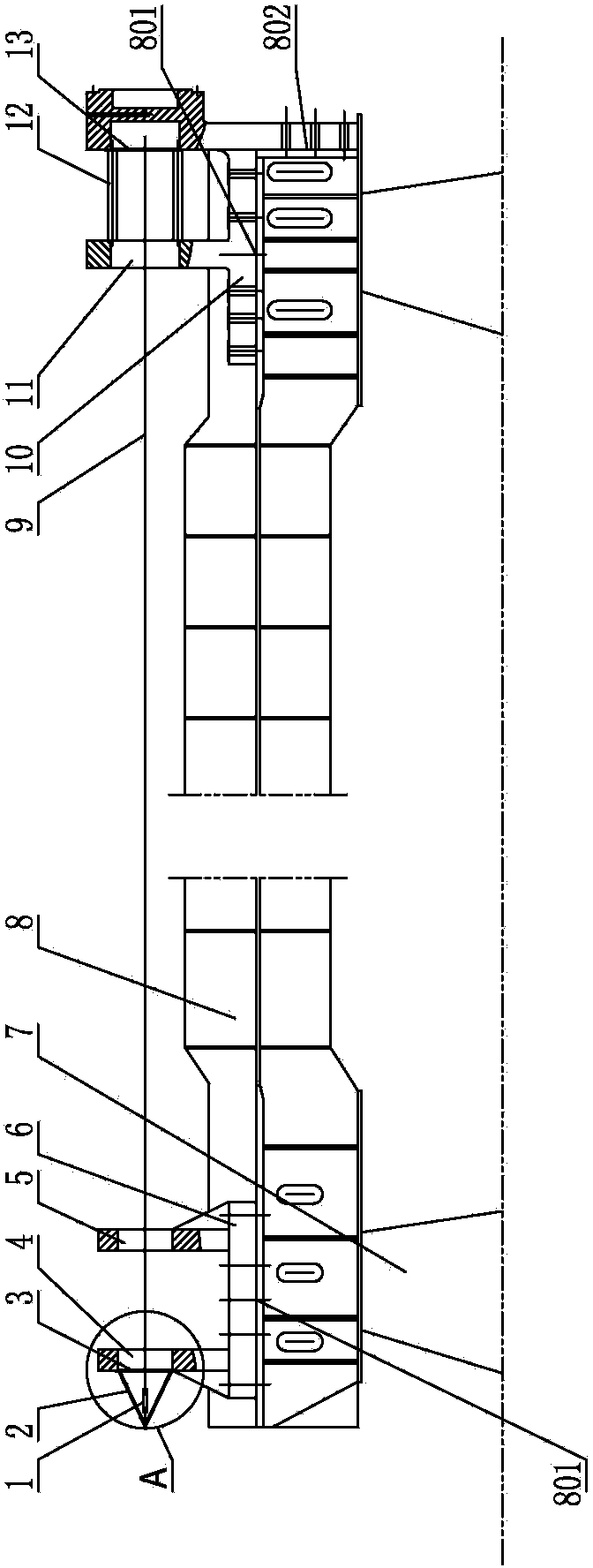
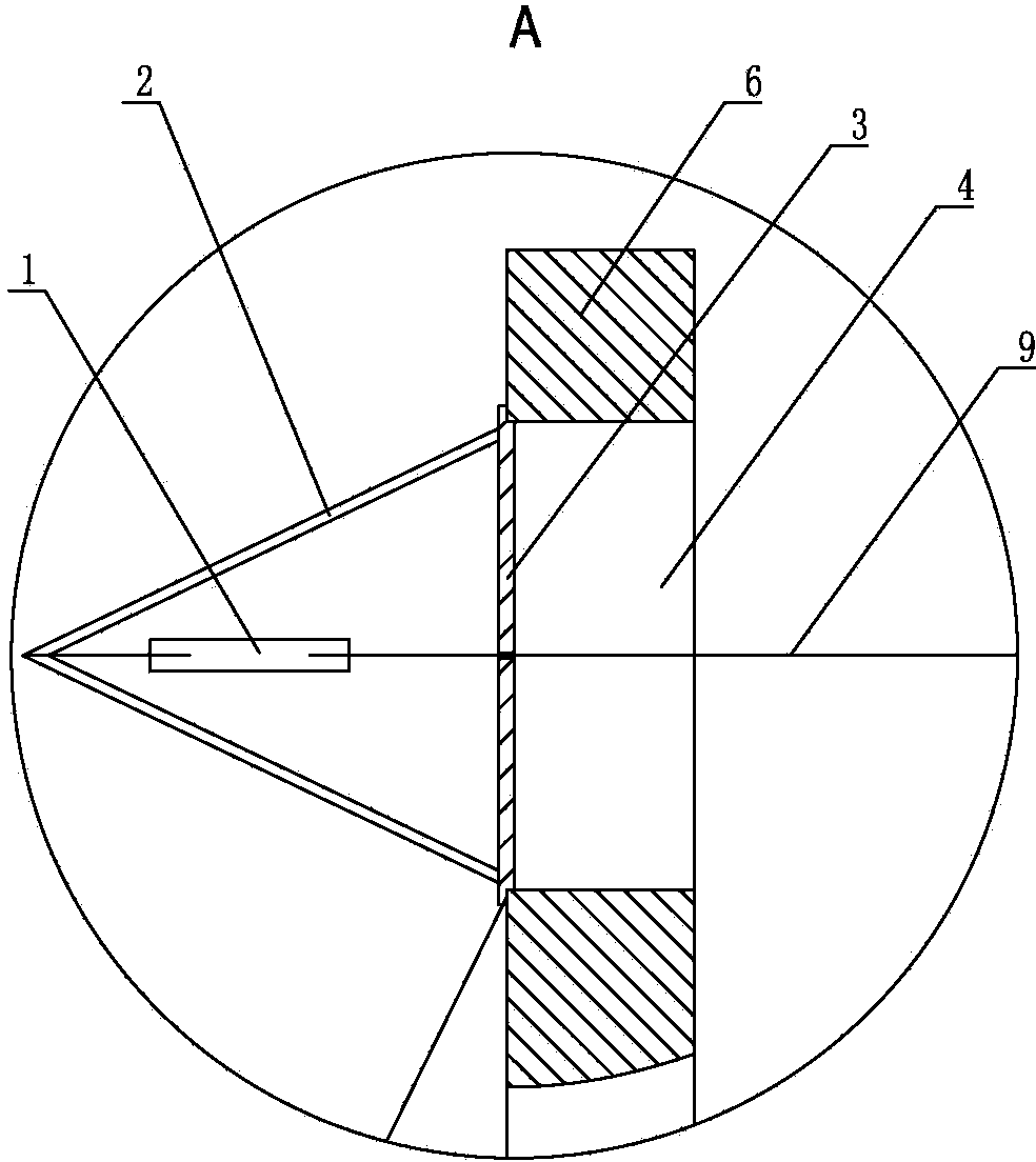
[0021] As shown in the figure, it is a method for adjusting the coaxiality of a triangular door shaft column, which includes the following steps:

[0022] 1) Place the end column 8 horizontally on the two support piers 7, so that the main installation surface of the end column 8 for installing the upper tie rod support 6 and the bottom pivot hinge seat 10 faces upward; measure with a level to make the end column 8, the main installation surface 801 for installing the upper tie rod support 6 and the bottom pivot hinge seat 10 is on the same horizontal plane; Just calibrate the level;

[0023] 2) Draw the central reference line on the symmetrical center of the upper surface of the end column 8, and put the side installation surface of the bottom pivot hinge seat 10 against the side installation surface 802 at the bottom of the end column 8, and the other installation surface of the bottom pivot hinge seat 10 Put it on the main mounting surface 801 of the end column 8, adjust th...


PUM


Abstract

The invention discloses a coaxiality adjusting method for a heel post of a triangular gate and belongs to the technical field of sluice gates. The method includes the steps that the center of a mounting hole of an upper pull rod support is determined through a first disk; the center of a mounting hole of a bottom pivot hinged support is determined through a second disk; a steel wire is pulled through the centers of the two mounting holes; the steel wire is calibrated to be in a horizontal state, and then a basic reference for calibrating a center line is provided, wherein the distance between the steel wire and the edge of each mounting hole which the steel wire penetrates through can be conveniently measured, the height can be adjusted through gaskets, and then the steel wire is fixed after being calibrated. Through the method, operation is convenient, the coaxiality of the heel post can be quickly and accurately calibrated, construction is convenient, and the requirement that the coaxiality error of the mounting holes does not exceed 0.5 millimeter can be met.

Description

technical field [0001] The invention relates to a gate, in particular to a positioning method for a gate shaft column of a triangular gate. Background technique [0002] In the existing water conservancy facilities, there is a triangular gate, the door body is fixed on the support arm, and the support arm is directly installed on the end column. When working, the end column rotates, and the support arm drives the door body to rotate to realize the opening and closing of the gate. The device consists of an end post for mounting the arm, on the end post there are two main mounting surfaces in the same plane, one main mounting surface for the upper tie rod support and the other main mounting surface for the bottom pivot hinge There is also a side mounting surface at the bottom of the end column, and there is also a side mounting surface on the bottom pivot hinge seat. There are two installation holes on the support for installing the top pivot; there are two installation holes...

Claims


Application Information

Patent Timeline
Patent Type & Authority Applications(China)
IPC IPC(8): G05D3/00G01B21/24
Inventor 王兵颜斌马志华顾明如顾世民凌建
Owner THE JIANGSU GENERAL FACTORY OF WATER CONSERVANCY MACHINERY
Why Eureka
Try Eureka