Motor rotor grinding device

A motor rotor and grinding technology, which is used in the manufacture of stator/rotor body, etc., can solve the problems of reducing processing efficiency, inconvenient workpiece clamping, and inability to realize automatic loading and unloading, and achieve the effect of improving processing efficiency.

Active Publication Date: 2014-07-09
SHANGHAI TOP MOTOR +2
View PDF7 Cites 2 Cited by
  • Summary
  • Abstract
  • Description
  • Claims
  • Application Information

AI Technical Summary

Problems solved by technology

[0003] The front and rear bearing positions and front and rear oil seal positions of the motor rotor are usually processed by a grinding machine. During processing, it is necessary to manually align the two ends of the workpiece (rotor to be processed) with the two clamping heads on the grinding machine, and then drive the two clamping heads Clamp the workpiece, and then manually lock the workpiece, so that the workpiece can rotate synchronously with the power output shaft of the grinding machine. The clamping of the workpiece is very inconvenient, thereby reducing the processing efficiency, and it is impossible to realize automatic loading and unloading

Method used


Image

  • Motor rotor grinding device
  • Motor rotor grinding device
  • Motor rotor grinding device

Examples


Embodiment Construction

[0018] The embodiments of the present invention will be described in further detail below in conjunction with the accompanying drawings, but the present embodiments are not intended to limit the present invention, and any similar structures and similar changes of the present invention should be included in the protection scope of the present invention.

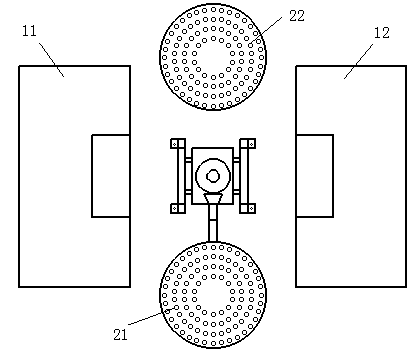
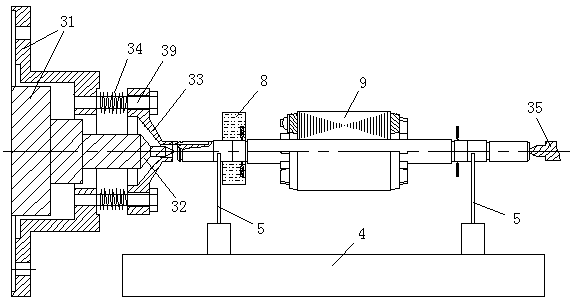
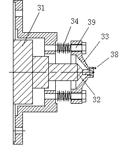
[0019] Such as Figure 1-Figure 4 As shown, a motor rotor grinding device provided by the embodiment of the present invention includes two grinding machines 11, 12, and the two grinding machines are arranged at intervals on the left and right, and a chucking disc 31 is fixed on the power output shaft of the left grinding machine 11, The right grinder 12 has a tailstock head 35 that can move left and right, and the right grinder 12 is equipped with a head drive component for driving the tailstock head 35 to move left and right;

[0020] A dial 33 that can move left and right and can rotate synchronously with the chucking disc 3...


PUM


Abstract

The invention relates to the technical field of motor manufacturing, in particular to a motor rotor grinding device to achieve the technical purpose of improving machining efficiency. The motor rotor grinding device comprises two grinding machines arranged on the left side and the right side in a spaced mode, a clamping disc is fixed to a power output shaft of the left grinding machine, the right grinding machine is provided with a tailstock ejector head capable of moving left and right, and the right grinding machine is provided with an ejector head drive component used for driving the tailstock ejector to move left and right. The clamping disc is provided with a shifting disc capable of moving left and right and synchronously rotating along with the clamping disc. The shifting disc is installed on the clamping disc through a plurality of shifting disc guiding columns sleeved with shifting disc springs. The middle of the shifting disc is provided with a boss protruding rightwards, the boss is used for clamping a workpiece, the center of the shifting disc is provided with a through hole, the through hole is internally provided with a fixed ejector head movably matched with the shifting disc, the fixed ejector head is fixedly connected with the clamping disc, and the center axis of the fixed ejector head coincides with the center axis of the tailstock ejector head. The motor rotor grinding device is suitable for grinding bearing positions and oil seal positions of a motor rotor.

Description

technical field [0001] The invention relates to motor manufacturing technology, in particular to a technology of a motor rotor grinding device. Background technique [0002] The motor is mainly composed of a stator, a rotor, a casing, and an end cover. The air gap between the stator and the rotor is very small, generally between 0.25 and 0.8mm. To ensure that the concentricity of the rotor and the stator is mainly guaranteed by the end covers at both ends. In addition, the machining accuracy of the rotor itself is more important, especially the concentricity requirements of the front and rear bearing positions and shaft extension, which directly affect the performance of the motor. And the air gap between the stator and the rotor. After the motor is energized, the stator winding generates a magnetic field to drive the rotor to rotate at a high speed. Therefore, the machining accuracy of the rotor determines the main performance of the motor such as noise, vibration, and star...

Claims


Application Information

Patent Timeline
IPC IPC(8): H02K15/02
Inventor 王明光
Owner SHANGHAI TOP MOTOR
Why Eureka
Try Eureka