Intravenous Flow Controller

A flow controller and infusion device technology, applied in the field of medical devices, can solve problems such as difficulty in accurately controlling the flow rate, large errors, and cumbersome processes, and achieve the effects of easy manufacture and use, low cost, and precise adjustment

Inactive Publication Date: 2015-09-23
HUANGHE S & T COLLEGE
View PDF9 Cites 0 Cited by
  • Summary
  • Abstract
  • Description
  • Claims
  • Application Information

AI Technical Summary

Problems solved by technology

At present, the adjustment of the intravenous flow rate during the treatment process is basically adjusted by the medical staff. During the water infusion process, once the patient has abnormalities or adverse reactions, the flow rate needs to be adjusted in time. When the infusion is about to end, the patient manually calls the nurse to change the dressing or stop the injection in time. Infusion, the process is more cumbersome
In addition, adjusting the flow rate by manual visual inspection has a large error, and it is difficult to accurately control the flow rate

Method used


Image

  • Intravenous Flow Controller
  • Intravenous Flow Controller

Examples


Embodiment Construction

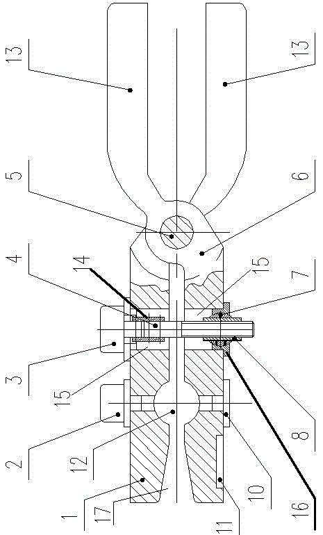
[0016] In the present invention, one end of the trumpet-shaped pipe inlet is used as the forward direction, and the reverse direction (the end of the manual clamping handle) is used as the backward direction.

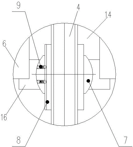
[0017] like figure 1 and figure 2 As shown, the intravenous injection flow controller of the present invention includes a pliers body, and the pliers body includes two halves that are hinged together. The two halves behind the hinge point are used as a manual clamping handle 13 for the user to hold and operate. The two halves of the side form a right clip body 1 and a left clip body 6 and are used to clamp the infusion set hose.

[0018] The middle parts of the left and right clamping bodies 6, 1 are symmetrically provided with arc grooves, and the arc grooves on the left and right clamping bodies 6, 1 are relatively arranged and enclose the infusion set hose clamping cavity 12; The left clamp body 6 or the right clamp body 1 on one side of the chamber 12 is provided...


PUM


Abstract

The invention discloses a flow controller for intravenous infusion. The flow controller for intravenous infusion comprises a pliers body. The pliers body comprises two half pieces which are hinged together. The portions, on the rear side of the hinge point, of the two half pieces are used as hand-operated clamping handles. The portions, on the front side of the hinge point, of the two half pieces form a right clamp body and a left clamp body. The middle portion of the left clamp body and the middle portion of the right clamp body are symmetrically provided with arc-shaped grooves which define an infusion set hose clamping cavity. The position, on one side of the infusion set hose clamping cavity, of the left clamp body or the right clamp body is provided with an infrared sensing emitter, and the position, on the other side of the infusion set hose clamping cavity, of the right clamp body or the left clamp body is provided with an infrared sensing receiver. An electric control unit and a setting and displaying module are arranged on the left clamp body or the right clamp body. The electric control unit is connected with the setting and displaying module, the infrared sensing emitter and the infrared sensing receiver respectively. The flow controller for intravenous infusion can accurately display the flow rate in the infusion set hose, and has the two functions of manually and automatically adjusting the flow rate in the infusion set hose; no mechanical adjustment in the manual and automatic switching process is needed, so the flow controller for intravenous infusion is very convenient to use.

Description

technical field [0001] The invention relates to the technical field of medical devices, in particular to the detection and control of liquid flow during intravenous injection. Background technique [0002] Intravenous injection (water infusion, drip) is a relatively common treatment method in the hospital. The flow rate of liquid medicine into the patient's vein (flow rate refers to the amount of liquid medicine injected into the human body per unit time) depends on the difference of each person's condition and the drug. Different and adjusted, so flow control is very important. At present, the adjustment of the intravenous flow rate during the treatment process is basically adjusted by the medical staff. During the water infusion process, once the patient has abnormalities or adverse reactions, the flow rate needs to be adjusted in time. When the infusion is about to end, the patient manually calls the nurse to change the dressing or stop the injection in time. Infusion, t...

Claims


Application Information

Patent Timeline
Patent Type & Authority Patents(China)
IPC IPC(8): A61M5/168
Inventor 张燕燕康运泽朱煜钰郭晓君陈会歌冯进权高云山
Owner HUANGHE S & T COLLEGE
Why Eureka
Try Eureka