
Gathering hopper of stirring station

The technology of mixing station and hopper is applied in the field of hopper of mixing station, which can solve the problems of easy wear and tear of the discharge port of the hopper, increase the workload of the staff, and affect the normal unloading of the hopper, so as to improve the discharge speed and shorten the time. The effect of working cycle and prolonging service life

Active Publication Date: 2014-07-16
SHANDONG MIX MACHINERY EQUIP
View PDF6 Cites 7 Cited by
  • Summary
  • Abstract
  • Description
  • Claims
  • Application Information

AI Technical Summary

Problems solved by technology

The common hopper consists of a bucket body made of four steel plates welded to each other at a certain angle in sequence. The top of the bucket body is provided with a square feeding port that matches the square installation port on the platform of the mixing station. The bottom of the bucket body is There is a circular discharge port. The disadvantage of this structure is that there is a dead angle for unloading at the joint between two adjacent steel plates, and the concrete is easily condensed and adhered to the joint between two adjacent steel plates, which requires regular cleaning by the staff. Clearing will affect the normal feeding of the bucket body, which increases the workload of the staff; the second is that the shape of the bucket body is irregular, and the liner cannot be installed, resulting in easy wear and tear at the outlet of the lower part of the hopper, short life, and increased user cost of use

Method used


Image

  • Gathering hopper of stirring station
  • Gathering hopper of stirring station
  • Gathering hopper of stirring station

Examples


Embodiment Construction

[0014] In order to clearly illustrate the technical features of this solution, the present invention will be described in detail below through specific implementation modes and in conjunction with the accompanying drawings.

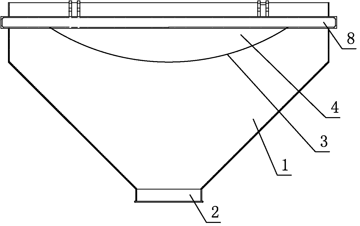
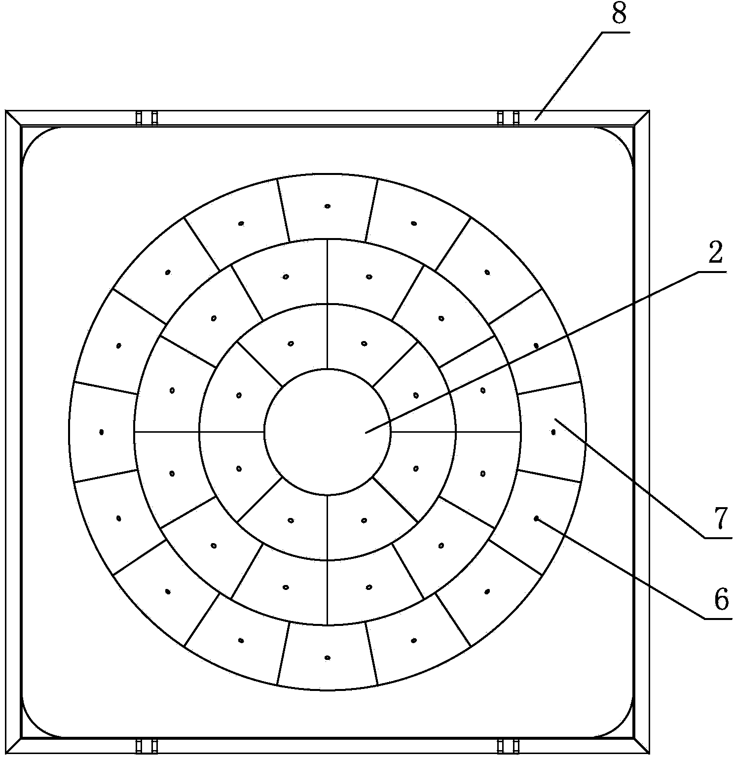
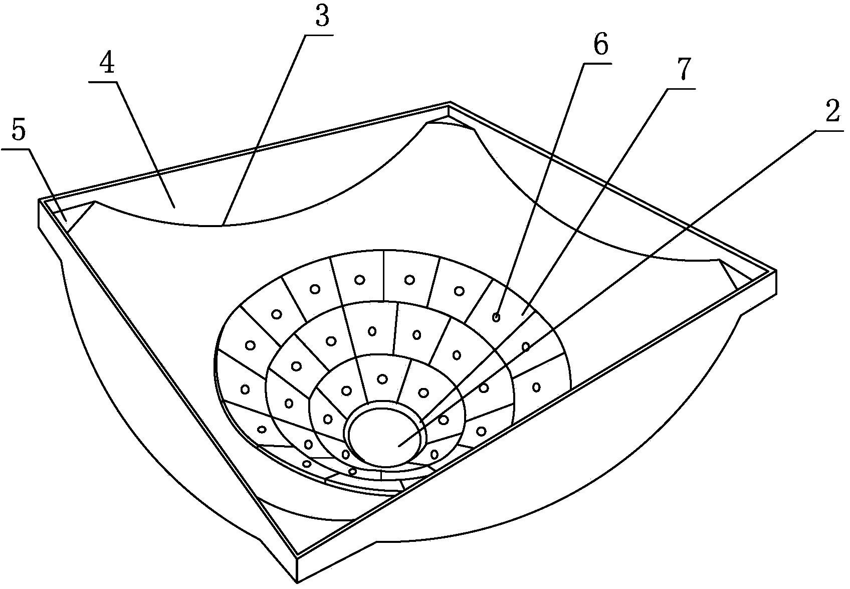
[0015] like Figure 1-3 As shown, a mixing hopper of a mixing station includes a conical material barrel 1, a feeding port 2 is provided at the bottom of the conical material barrel 1, and four uniform sizes are evenly arranged on the top of the conical material barrel 1 along the circumference. The arc-shaped notch 3 of each arc-shaped notch 3 is provided with a vertically arranged baffle plate 4 respectively, and the ends of adjacent two baffle plates 4 are welded vertically, and the four baffle plates 4 surround and stir The square feeding port matched with the square mounting port on the platform of the station, the top of the conical barrel 1 between two adjacent arc-shaped notches 3 and the two-phase welded stopper set at the two arc-shaped notches ...


PUM

PropertyMeasurementUnit
diameteraaaaaaaaaa

Abstract

The invention discloses a gathering hopper of a stirring station. The gathering hopper comprises a conical material barrel, wherein a material blanking port is formed in the bottom of the conical material barrel; four arc-shaped notches with the same size are uniformly formed in the circumference of the top end of the conical material barrel; a material blocking plate is vertically arranged at each arc-shaped notch; the ends of each two adjacent material blocking plates are vertically welded; the four material blocking plates define a square feed port which is matched with the square installation port on the platform of the stirring station; a seal plate is arranged at the clearance which is between the top end of the conical material barrel between each two arc-shaped notches and the welded materials plates arranged at the two arc-shaped notches. The structure of the gathering hopper is reasonable in design; the conical material barrel is adopted and the inner surface is arc-shaped, so that discharge dead angle does not exist, concrete is avoided from adhering to the material barrel and the normal material blanking of the conical material barrel is guaranteed; besides, a replaceable arc-shaped lining plate is additionally arranged at the lower part of the inner side of the conical material barrel, so that the service life of the gathering hopper is greatly prolonged.

Description

Technical field: [0001] The invention relates to a mixing hopper for a mixing station. Background technique: [0002] The hopper of the concrete mixing plant is the discharge device of the concrete mixing plant. Its main function is to transfer the mixed concrete from the mixer to the concrete transport vehicle. The common hopper consists of a bucket body made of four steel plates welded to each other at a certain angle in sequence. The top of the bucket body is provided with a square feeding port that matches the square installation port on the platform of the mixing station. The bottom of the bucket body is There is a circular discharge port. The disadvantage of this structure is that there is a dead angle for unloading at the joint between two adjacent steel plates, and the concrete is easily condensed and adhered to the joint between two adjacent steel plates, which requires regular cleaning by the staff. Clearing will affect the normal feeding of the bucket body, which...

Claims


Application Information

Patent Timeline
Patent Type & Authority Applications(China)
IPC IPC(8): B28C7/16
CPCB28C7/16
Inventor 梁纪民王福君
Owner SHANDONG MIX MACHINERY EQUIP
Learn More