Inkjet coding machine nozzle support frame structure

A coding machine and supporting frame technology, applied in printing and other directions, can solve problems such as inconvenient position adjustment and unfavorable coding efficiency, and achieve the effects of convenient operation, increased adaptability, and beneficial coding efficiency.

Active Publication Date: 2016-03-02
CHINA CHENGDU ANIMAL HUSBANDRY IND BIOPHARM
View PDF5 Cites 0 Cited by
  • Summary
  • Abstract
  • Description
  • Claims
  • Application Information

AI Technical Summary

Problems solved by technology

[0004] In order to solve the problem of inconvenient adjustment of the position of the nozzle of the inkjet coding machine relative to the material platform in the above-mentioned prior art, which is not conducive to the coding efficiency, the present invention provides a support frame structure for the nozzle of the inkjet coding machine

Method used


Image

  • Inkjet coding machine nozzle support frame structure
  • Inkjet coding machine nozzle support frame structure

Examples


Embodiment 1

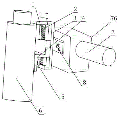
[0020] Such as figure 1 and figure 2 , the nozzle support structure of the inkjet coding machine provided by the present invention includes a mounting frame 7 and an inkjet head connection block 4 connected to the mounting frame 7, and also includes a height adjustment part 3; the height adjustment part 3 is provided with The height fine adjustment bolt 2 and the guide rod 1, the two ends of the guide rod 1 are fixedly connected to the height adjustment part 3, the height adjustment part 3 is also provided with a bolt hole, the height fine adjustment bolt 2 is partially located in the bolt hole, and The height fine adjustment bolt 2 can rotate around the bolt hole and the positional relationship between the height fine adjustment bolt 2 relative to the height adjustment part 3 does not change, the height fine adjustment bolt 2 and the guide rod 1 are parallel to each other, the inkjet head connecting block 4 is connected The bolts 2 are threaded, and the inkjet head connecti...

Embodiment 2

[0023] This embodiment is further limited on the basis of embodiment 1: as figure 1 and figure 2 , in order to make the height of the height adjustment part 3 relative to the installation frame 7 linearly adjustable within a small range, the height adjustment part 3 is also provided with a bar-shaped hole 8, and the height adjustment part 3 and the installation frame 7 are arranged on a bar-shaped The connection bolts of hole 8 are fixedly connected.

Embodiment 3

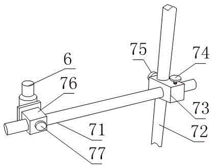
[0025] This embodiment is further limited on the basis of embodiment 1: as figure 1 and figure 2 , the inkjet head connection block 4 includes two flat plates parallel to each other and a connecting plate connecting the two flat plates, any one of which is provided with fine-tuning threaded holes and guide rod grooves, and the other plate is provided with a plurality of thick Adjust the bolt hole or a bar-shaped hole, and be provided with height coarse-adjusting bolt 5 in any coarse-adjusting bolt hole or bar-shaped hole. The inkjet head connection block 4 of the above structural form is simple in structure, which is conducive to reducing the weight and manufacturing cost of the inkjet head connection block 4. At the same time, the above structural form is convenient to reserve enough space for adjusting the height of the coarse adjustment bolt 5; The height coarse adjustment bolt 5 is used to connect the inkjet head 6, and adopts the structural form of multiple coarse adjus...


PUM


Abstract

The invention discloses a spray head support frame structure of an inkjet coding machine. The spray head support frame structure of the inkjet coding machine comprises an installing rack and an ink jet head connecting block. The spray head support frame structure of the inkjet coding machine further comprises a height adjusting part; a height fine adjusting bolt and a guide rod are arranged on the height adjusting part, the two ends of the guide rod are fixedly connected to the height adjusting part, a bolt hole is further formed in the height adjusting part, the height fine adjusting bolt is partially located in the bolt hole, the height fine adjusting bolt can rotate around the bolt hole and the position of the height fine adjusting bolt relative to the height adjusting part does not change, the height fine adjusting bolt is parallel to the guide rod, the ink jet head connecting block is connected with the height fine adjusting bolt in a threaded mode, a guide rod groove is further formed in the ink jet head connecting block, the guide rod is partially located in the guide rod groove, and the height adjusting part is fixedly connected with the installing rack. According to the spray head support frame structure of the inkjet coding machine, adjustment of the position of an ink jet mouth of the inkjet coding machine relative to a material platform is convenient, so that code printing efficiency and the code printing effect are facilitated.

Description

technical field [0001] The invention relates to a printing and coating equipment for a medicine packaging box, in particular to a support frame structure for a spray head of an inkjet coding machine. Background technique [0002] The coding principle of the inkjet coding machine is to apply a certain pressure to the ink in the system by controlling its internal gear pump or supplying compressed gas from its outside, so that the ink is ejected through a nozzle with an aperture of tens of microns, and the ink adheres to different positions on the product surface , Form the required various characters, patterns and other logos on the product. [0003] Existing coding machines are used for packaging boxes in drug production enterprises. The inkjet head is fixedly connected to the installation frame and located above the material platform. The coding area on the packaging box needs to face the nozzle of the inkjet head. When the external dimension changes or the coding area chan...

Claims


Application Information

Patent Timeline
Patent Type & Authority Patents(China)
IPC IPC(8): B41J2/01
Inventor 廖成斌邹学刚
Owner CHINA CHENGDU ANIMAL HUSBANDRY IND BIOPHARM
Why Eureka
Try Eureka