Bottle cap output mechanism
A technology of output mechanism and bottle cap, which is applied to conveyors, rotary conveyors, transportation and packaging, etc., can solve the problems of uncontrolled front and back sides of bottle caps and low efficiency, and achieve the effect of simple structure and improved efficiency.
- Summary
- Abstract
- Description
- Claims
- Application Information
AI Technical Summary
Benefits of technology
Problems solved by technology
Method used
Image

Examples
Embodiment 1
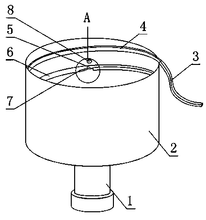
[0022] Such as figure 1 and figure 2 , a bottle cap output mechanism provided by the present invention includes a cylindrical material barrel 2, a helical spiral guide rail 6 is fixedly connected to the inner wall of the material barrel 2, and a bottle cap is provided at the bottom of the material barrel 2. Cap brake device, the inlet end of the spiral guide rail 6 is connected with the bottle cap brake device, and the outlet end of the spiral guide rail 6 is also connected with the output guide rail 3, and a gap 5 is also provided at any position on the spiral guide rail 6, and the The gap 5 is located on the side of the spiral guide rail 6 close to the axis of the material barrel 2, and the inner wall of the material barrel 2 at the gap 5 is also provided with a protrusion 8 that protrudes relative to the inner wall of the material barrel 2. The bottle cap braking device It includes a driving motor 1 and a turntable connected to the rotor of the driving motor 1 .
[0023]...
Embodiment 2
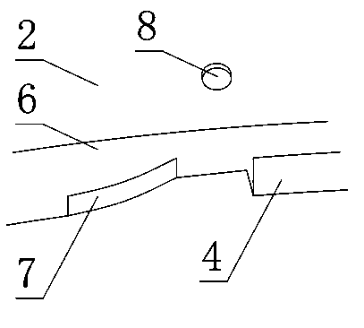
[0025] This embodiment is further limited on the basis of embodiment 1: as figure 1 and figure 2 The spiral guide rail 6 at the front end of the gap 5 is also provided with a polycondensation port 7, the polycondensation port 7 includes a section of the spiral guide rail width gradual change section on the spiral guide rail 6 and a rib fixed on the free side of the spiral guide rail width gradual change section, polycondensation The rear end of the port 7 is in contact with the notch 5, and the distance between the material barrel 2 and the rib decreases linearly from the front end to the rear end of the polycondensation port 7.
[0026] The above structure makes the bottle cap close to the notch 5 before the spiral guide rail 6, and the guiding effect of the rib to the bottle cap makes the bottle cap move close to the inner wall of the material barrel 2, so that as long as the larger diameter end of the bottle cap is in contact with the screw The bottle caps fitted by the g...
Embodiment 3
[0028] The present embodiment is further limited on the basis of embodiment 1: as figure 1 and figure 2 , in order to facilitate the smooth movement of the bottle caps along the spiral guide rail 6 under mutual extrusion, the included angle between any tangent line on the spiral guide rail 6 and the horizontal plane is not greater than 20°.
[0029] In order to reduce the total drop of the bottle cap on the spiral guide rail 6 during the movement, the free side of the spiral guide rail 6 is higher than the connection side of the spiral guide rail 6 and the material barrel 2 by 1-3 mm.
PUM
 Abstract
Description
Claims
Application Information