Supercharge Your Innovation With Domain-Expert AI Agents!

Container Flooring Equipment

A container and floor technology, applied in the field of container floor paving equipment, can solve the problems of complex structure, low floor paving efficiency, poor synchronization, etc., and achieve the effect of simplifying equipment structure, fewer equipment parts, and high reliability

Active Publication Date: 2018-01-19
CHINA INTERNATIONAL MARINE CONTAINERS (GROUP) CO LTD +1
View PDF1 Cites 0 Cited by
  • Summary
  • Abstract
  • Description
  • Claims
  • Application Information

AI Technical Summary

Problems solved by technology

Although the wooden floor laying device reduces the labor intensity of workers and improves work efficiency, the wooden floor laying device needs to dig a pit, so the equipment investment is large and the structure is complicated; and the wooden floor laying device includes many lifting frames, each The lifting frame needs to be equipped with a push cylinder or a pushing oil cylinder as the lifting drive device, so the cost is relatively high, and each lifting frame works independently, but when the floor is transported, the lifting frames need to cooperate with each other, so the synchronization is poor, resulting in The floor transmission is not smooth, and the number of lifting frames is large, so the probability of damage or malfunction is high. Once one lifting frame is damaged or not working properly, it will cause the entire wooden floor laying device to go on strike. Therefore, the wooden floor laying device Poor reliability; in addition, when the wooden floor laying device is laying the floor, it needs to wait for the container to be transported into place, and then place the floor on the lifting frame for floor transmission, so the container placement process and the floor placement process cannot be carried out synchronously. Wasted waiting time, resulting in inefficient flooring

Method used


Image

  • Container Flooring Equipment
  • Container Flooring Equipment
  • Container Flooring Equipment

Examples


Embodiment Construction

[0039] In order to further illustrate the principle and structure of the present invention, preferred embodiments of the present invention will now be described in detail with reference to the accompanying drawings.

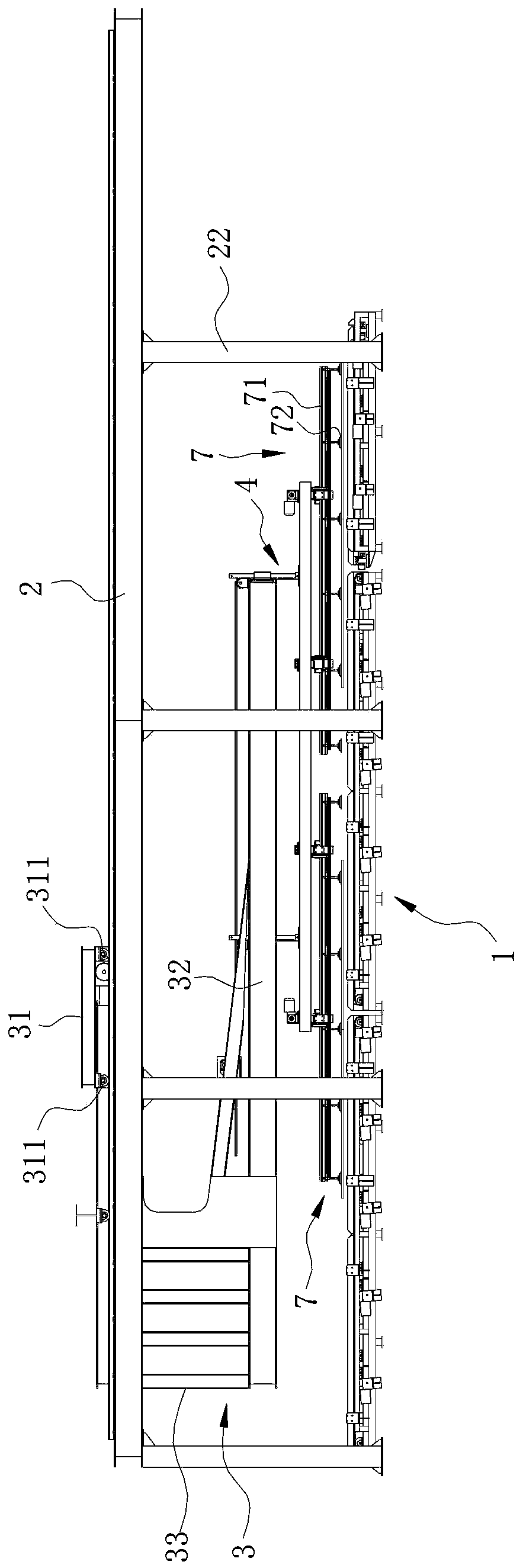
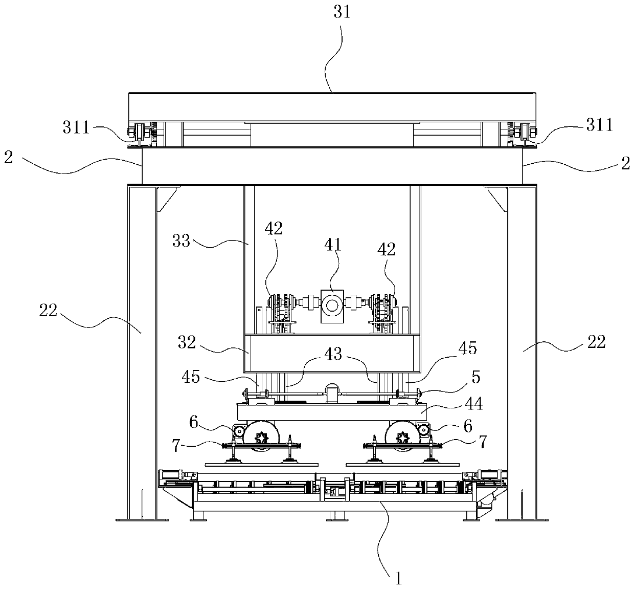
[0040] The container floor pavement equipment of the present invention is arranged on the outside of the container door end. When describing the orientation, the length direction of the container is taken as the longitudinal direction, the width direction of the container is taken as the transverse direction, and the end close to the container door end is taken as the front end, and the side far away from the container door end is taken as the front end. One end is the backend.

[0041] refer to figure 1 and figure 2 , the container floor pavement equipment of the present invention comprises: the material preparation mechanism 1 that is arranged on the ground, the track 2 that is arranged longitudinally, the walking mechanism 3 that can move along the track 2, ...


PUM


Abstract

A container floor paving equipment and paving method, the paving equipment includes: a material preparation mechanism for transporting the floor to a floor grabbing station, a set of tracks arranged in the longitudinal direction, and a track that can walk back and forth along the track The walking mechanism includes at least one lifting mechanism that can be raised and lowered relative to the walking mechanism, and at least one grabbing mechanism for grabbing the floor. The paving method includes: the floor is transported to the floor grabbing station by the material preparation mechanism; after that, the lifting mechanism drives the grabbing mechanism to descend to grab the floor, and the lifting mechanism drives the grabbing mechanism and the floor to rise, and finally, the walking The mechanism drives the grabbing mechanism and the floor to translate to the inside of the container. After the floor is completely moved into the container, the lifting mechanism is lowered, which drives the grabbing mechanism down, releases the floor, and completes the paving. The floor paving equipment has good synchronization and high reliability, and the floor paving method has high paving efficiency and saves time and effort.

Description

technical field [0001] The invention relates to a container manufacturing equipment, in particular to a container floor paving equipment. Background technique [0002] A container usually includes a horizontally arranged underframe, a door end erected at one end of the lengthwise direction of the underframe, an end wall erected at the other end of the lengthwise direction of the underframe, and two Side walls and roof panels positioned horizontally on top of the door ends, side walls, and end walls. A floor is laid on the base frame, and the floor can be a wooden floor, a steel floor, or a composite floor. During the production of containers, it is usually necessary to assemble the bottom frame, door end, end wall and side walls first, and then lay a floor on the bottom frame in the container to meet the needs of cargo transportation. [0003] The early paving of container wood flooring adopted a completely manual method, that is to say, multiple workers carried out the ha...

Claims


Application Information

Patent Timeline
Patent Type & Authority Patents(China)
IPC IPC(8): B65G37/00B65G47/88B65G47/91B65G47/92B65D90/00
Inventor 范健
Owner CHINA INTERNATIONAL MARINE CONTAINERS (GROUP) CO LTD
Features
  • R&D
  • Intellectual Property
  • Life Sciences
  • Materials
  • Tech Scout
  • Unparalleled Data Quality
  • Higher Quality Content
  • 60% Fewer Hallucinations
Learn More