Rotary wheel type spring press-conveying device

A runner type and runner technology, which is applied to the device field of bagging machines, can solve problems such as restricting the production speed of bagged springs, and achieve the effect of high-speed production.

Inactive Publication Date: 2014-07-16
FOSHAN YUANTIAN MATTRESS MACHINERY
View PDF9 Cites 7 Cited by
  • Summary
  • Abstract
  • Description
  • Claims
  • Application Information

AI Technical Summary

Problems solved by technology

However, the two processes of spring forming and spring bagging can achieve high-speed production. Obvio

Method used


Image

  • Rotary wheel type spring press-conveying device

Examples


Embodiment Construction

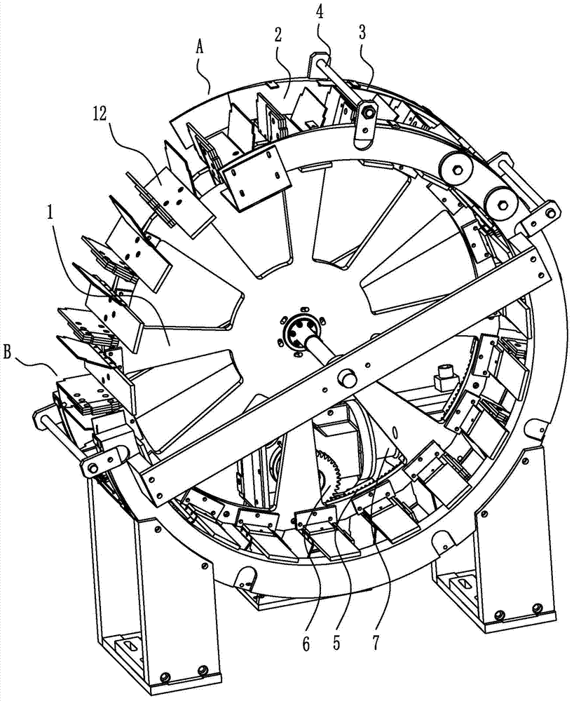
[0009] Such as figure 1 As shown, a runner type spring pressure feeding device includes a runner 1, and the runner 1 is provided with clamping positions 12 for clamping springs at intervals along its circumference, and both sides of the runner clamping positions 12 are provided with fixed The side block 2, the outer circumference of the runner 1 is provided with a fixed outer block 3, the side block 2 and the outer block 3 extend from the spring inlet position A to the spring outlet position B along the direction of rotation of the runner 1, and the side blocks 2 on both sides The distance between them gradually narrows along the direction of rotation of the runner. The side block 2 and the outer block 3 form an arc-shaped chute that can accommodate the sliding of the spring, and the runner 1 rotates in the arc-shaped chute, and with the rotation of the runner 1, the spring that falls on the runner clamping position 12 is locked. Sliding in the ring chute. Since the distance...


PUM


Abstract

The invention discloses a rotary wheel type spring press-conveying device. The rotary wheel type spring press-conveying device comprises a rotary wheel, clamping positions used for clamping springs are distributed in the circumferential direction of the rotary wheel at intervals, fixed side blocks are arranged on both sides of each clamping position of the rotary wheel, fixed outer blocks are arranged on the periphery of the rotary wheel, the side blocks and the outer blocks extend to spring outlet positions from spring inlet positions in the direction of rotation of the rotary wheel, and the distance between the side blocks on the two sides of each clamping position becomes narrower and narrower in the direction of rotation of the rotary wheel. The multiple clamping positions are distributed in the circumferential direction of the rotary wheel of the rotary wheel type spring press-conveying device, after springs are machined and formed, the springs sequentially fall into the clamping positions of the rotary wheel, and as the rotary wheel rotates, the springs are conveyed to an inlet of a clamping-conveying belt connected with the spring outlet positions and conveyed away through the clamping-conveying belt. The rotary wheel type spring press-conveying device can be connected between a high-speed running spring forming device and the clamping-conveying belt and is responsible for spring conveying, and thus high-speed production of bagged springs can be achieved.

Description

technical field [0001] The invention relates to the technical field of mattress machinery, in particular to a device that can press and send formed springs to a bagging machine. Background technique [0002] Pocket springs for mattresses are made by putting the springs in a non-woven bag. Usually, before the springs are bagged, the springs must be compressed to a certain extent to make them have proper elasticity. In production, the springs processed by the spring forming device are sent to the conveyor belt by the manipulator. It gradually shrinks along the conveying direction, so that the spring can be gradually compressed during the conveying process. Since the traditional way of sending the formed spring to the pinch belt is the way of manipulator, the manipulator needs to first pick up the spring from the forming device, then transfer it to the input port of the pinch belt, and finally return to clamp it. a spring. Every time the transfer of a spring is completed, th...

Claims


Application Information

Patent Timeline
IPC IPC(8): B65G47/84
Inventor 李德锵
Owner FOSHAN YUANTIAN MATTRESS MACHINERY
Why Eureka
Try Eureka