Continuous manufacturing system and continuous manufacturing method of liquid crystal display element

A technology for liquid crystal display elements and manufacturing systems, applied in the direction of chemical instruments and methods, control lamination, and other household appliances

Active Publication Date: 2012-04-18
NITTO DENKO CORP
View PDF6 Cites 7 Cited by
  • Summary
  • Abstract
  • Description
  • Claims
  • Application Information

AI Technical Summary

Problems solved by technology

In this case, as in Patent Document 2, speed control is performed so that when the next film sheet of the film sheet in progress reaches the front end of the peeling unit (when the rear end of the film sheet in progress is at the When the front end of the peeling unit) becomes V1

Method used


Image

  • Continuous manufacturing system and continuous manufacturing method of liquid crystal display element
  • Continuous manufacturing system and continuous manufacturing method of liquid crystal display element
  • Continuous manufacturing system and continuous manufacturing method of liquid crystal display element

Examples


no. 1 Embodiment approach

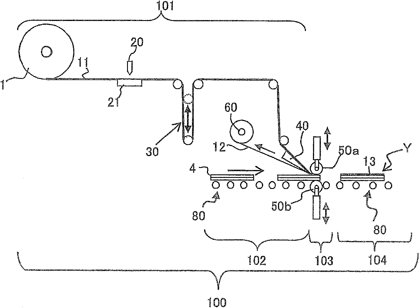
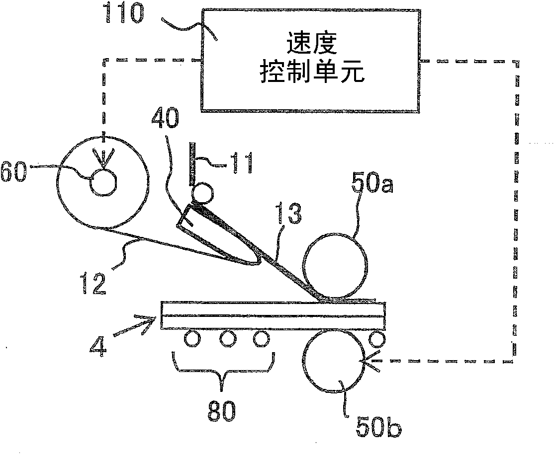
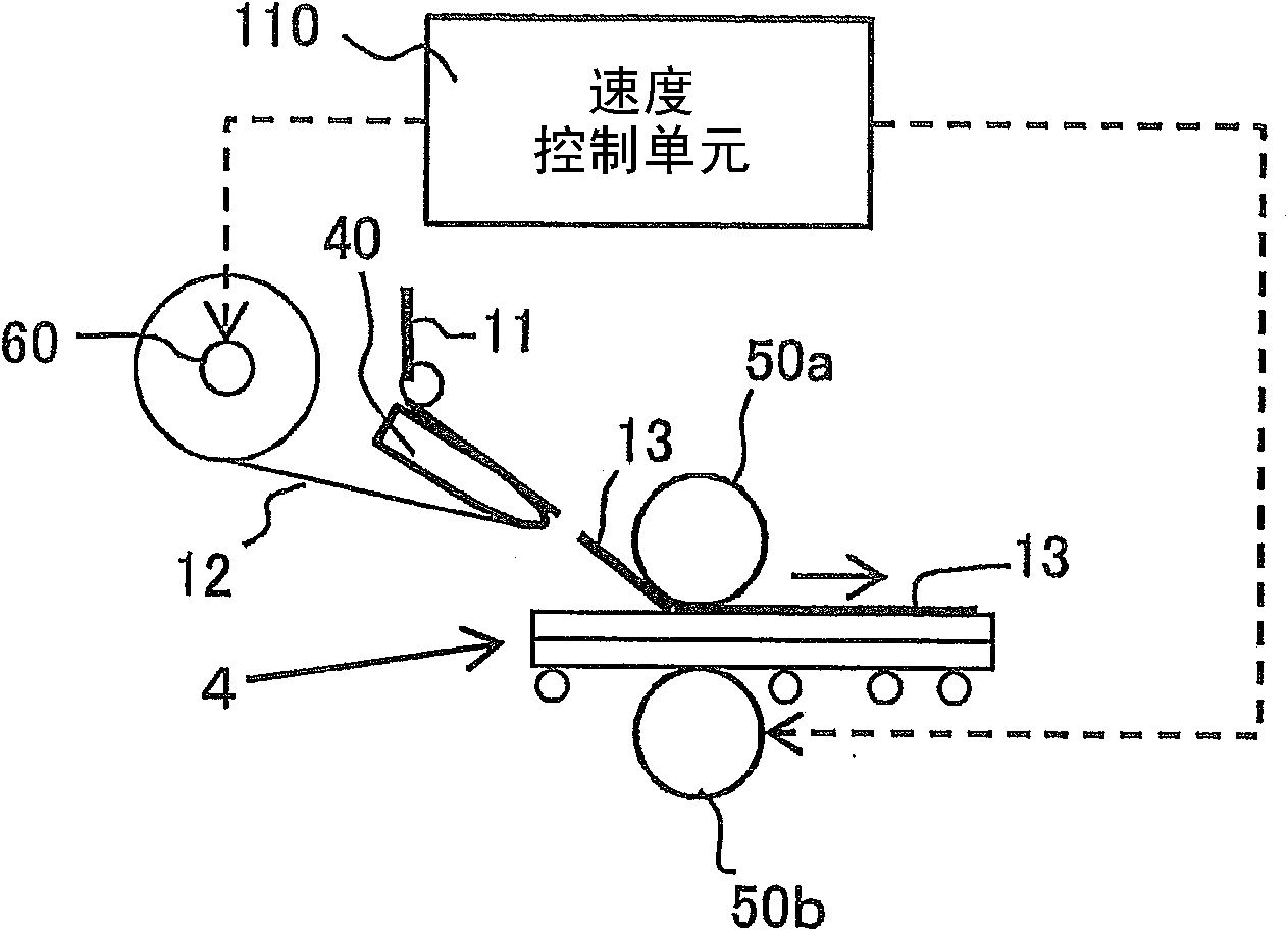
[0054] The continuous manufacturing system of the liquid crystal display element of the present embodiment has: a peeling unit that, when the film sheets of the polarizing film including the adhesive are adjacent to each other, uses the carrier film formed through the adhesive as the inner side. Turning over at the front end to peel off the film sheet from the carrier film; a winding unit that winds up the carrier film from which the film sheet has been peeled off by the peeling unit; and a sticking unit that, while transporting the liquid crystal panel, A liquid crystal display element is formed by affixing the film sheet peeled by the peeling unit to the liquid crystal panel via the adhesive. Moreover, it also has a speed control unit, which controls the winding unit and the pasting unit so that: in the pasting process of pasting the film sheet to the liquid crystal panel, the film sheet is moved toward the During the period from the sticking start time when the sticking of ...

Embodiment

[0080] use figure 1 In the production system of , a film sheet of a polarizing film was attached to a liquid crystal panel (40 inches) on both sides from the long side, and the presence or absence of air bubbles was evaluated.

[0081] When the rear end of the film sheet being pasted is located at any one of the upstream position in the conveying direction (comparative example) or the downstream position in the conveying direction (embodiment) with respect to the front end of the peeling unit, when the take-up speed V1 of the carrier film is In the case of decelerating from the sticking speed V2, the state of bubble generation in the liquid crystal panel after sticking the film sheet was evaluated.

[0082] exist Figure 6 In the shown embodiment 1, the deceleration is carried out on the premise of making the winding speed V1 and the sticking speed V2 the same speed from the highest speed. After the front end of the coil, only the winding speed V1 is further decelerated so t...


PUM

PropertyMeasurementUnit
thicknessaaaaaaaaaa
thicknessaaaaaaaaaa
thicknessaaaaaaaaaa

Abstract

The invention relates to a continuous manufacturing system of a liquid crystal display element. The continuous manufacturing system is provided with a peeling unit which is used to peel a film sheet from a carrier film, a reeling unit which is used to reel the carrier film, a pasting unit which is used to paste the film sheet to a liquid crystal panel via an adhesive to form a liquid crystal display element, a speed control unit which is used to control the reeling unit and the pasting unit. In the process that the film sheet is pasted on the liquid crystal panel, during the period from the film sheet is pasted on the liquid crystal panel to the film sheet is peeled from the carrier film via the front end of the peeling unit, the carrier film reeling speed of the reeling unit V1 and the pasting speed of the pasting unit V2 satisfy the equation: V1 is equal to V2. The moment before the film sheet is peeled from the carrier film via the front end of the peeling unit to be pasted on the liquid crystal panel and after the film sheet is pasted on the liquid crystal panel, the V1 is smaller than V2. The continuous manufacturing system can prevent the adhesive dropping and adhesive residual when the polarized film is pasted on the liquid crystal panel.

Description

technical field [0001] The present invention relates to a liquid crystal display element continuous manufacturing system and a liquid crystal display element continuous manufacturing method for forming a liquid crystal display element by adhering a polarizing film sheet peeled from a carrier film to a liquid crystal panel via an adhesive. Background technique [0002] A kind of continuous manufacturing method of such a liquid crystal display element is known, that is: use the carrier film of the film sheet formed with the polarizing film through the adhesive as the inside of the peeling unit to turn over at the front end of the peeling unit to polarize the polarizing film. The film sheet of the film is peeled from the carrier film together with the adhesive, and while the liquid crystal panel is being transported, the peeled film sheet of the polarizing film is attached to the liquid crystal panel via the adhesive by the sticking unit (Patent Document 1 ). [0003] In the c...

Claims


Application Information

Patent Timeline
Patent Type & Authority Applications(China)
IPC IPC(8): G02F1/1335G02F1/1333
CPCB32B2457/20B32B37/12G02F1/133528B32B41/00G02F1/1303B32B2309/105G02F1/1335G02F1/13
Inventor 秦和也平田聪近藤诚司
Owner NITTO DENKO CORP
Why Eureka
Try Eureka