A yarn guiding device

A yarn guide and guide block technology, applied in textiles and papermaking, etc., can solve the problems of slow fiber twisting speed, slow air rotation speed, weak twist yarn, etc., to reduce the generation mechanism, increase twisting speed, The effect of increasing the breaking strength

Active Publication Date: 2016-02-03
江阴市华方新技术科研有限公司
View PDF5 Cites 4 Cited by
  • Summary
  • Abstract
  • Description
  • Claims
  • Application Information

AI Technical Summary

Problems solved by technology

[0003] In the spinning device used above, since the guide surface on the fiber guide member is made into a slightly twisted shape (that is, a slight spiral ), so the processing of the guide parts is difficult, and the vortex chamber of this spinning device has a large space, the airflow inside the vortex chamber rotates at a slow speed, and the eddy current twists the fibers slowly, which cannot fully enhance the breaking strength of the yarn. It is easy to produce weakly twisted yarn under the same pressure and number of tangential jet holes

Method used


Image

  • A yarn guiding device
  • A yarn guiding device

Examples


Embodiment Construction

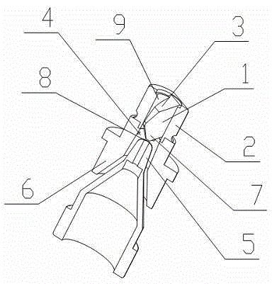
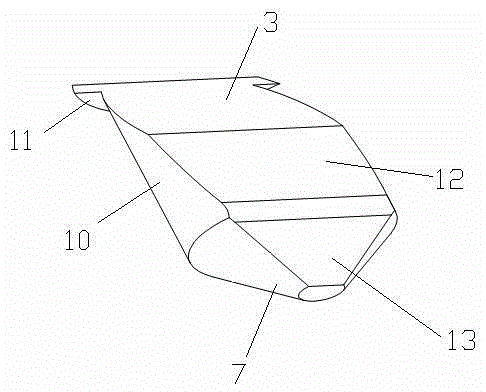
[0027] see figure 1 , figure 2 , a yarn guiding device of the present invention, which includes a guiding block 1, a casing 2 and a vortex tube 6, the guiding block 1 is arranged in the casing 2, and the guiding block 1 includes a cylindrical guiding block The base 10 and the conical boss 7, the conical boss 7 is arranged on the front end of the cylindrical guide block base 10, the rear end of the cylindrical guide block base 10 is provided with a positioning block 11, the The front end of the cylindrical guide block base 10 is cut to the middle to form the second guide surface 12, and the front of the cylindrical guide block base 10 to the rear end positioning block 11 is cut to form the first guide surface 3. The slope of the guide surface 3 is greater than that of the second guide surface 12. The front end of the cylindrical guide block base body 10 is cut off from the front end of the conical boss 7 to form a third guide surface 13. The second guide surface 12 It transi...


PUM


Abstract

The invention relates to a yarn guiding device, and belongs to the technical field of textile machinery. The yarn guiding device comprises a guiding block (1), a shell (2) and a vortex tube (6), wherein the guiding block (1) is arranged in the shell (2), the guiding block (1) comprises a cylindrical guiding block base body (10) and a conical boss (7), a positioning block (11) is arranged at the rear end of the cylindrical guiding block base body (10), the front side of the portion, from the front end to the middle, of the cylindrical guiding block base body (10) is cut off to form a second guiding face (12), the front side of the portion, from the middle to the positioning block (11) at the rear end, of the cylindrical guiding block base body (10) is cut off to form a first guiding face (3), and the front side of the portion from the front end of the cylindrical guiding block base body (10) to the front end of the conical boss (7) is cut off to form a third guiding face (13). According to the yarn guiding device, the rotational speed of air flow inside a swirl chamber can be increased, the twisting speed of yarn is high, the yield of the final yarn is increased, and the breaking strength of the final yarn is improved.

Description

technical field [0001] The invention relates to a yarn guiding device, which belongs to the technical field of textile machinery. Background technique [0002] Currently, methods and devices are known for producing these spun yarns using swirling air streams. Chinese patent CN1038438C discloses a spinning device, which includes a fiber guiding part, which includes a slightly twisted guiding surface, and forms a fiber feeding channel with the inlet wall of the spinning device. The fiber guiding member is made roughly in the shape of a truncated cone with a large diameter at the top end and a small diameter at the bottom end, and is twisted slightly along the slit in the swirling direction of the swirling airflow, and then moves along the longitudinal direction from the large diameter at the top end. A shape cut off on one side. A concentric guide needle for twist resistance is also installed in the exit area of ​​the fiber feed channel. An annular vortex chamber is install...

Claims


Application Information

Patent Timeline
Patent Type & Authority Patents(China)
IPC IPC(8): D01H13/04
Inventor 陈国樑吴奕宏陆荣海高勇
Owner 江阴市华方新技术科研有限公司
Why Eureka
Try Eureka