Bridge expansion joint device with multiple water stop structures
An expansion joint and water-stop technology, applied in bridges, bridge parts, bridge construction, etc., can solve the problems of loss of water-stop function, failure to stop water, difficult to clean, etc., to reduce the probability of warping and improve the compression resistance. ability, the effect of enhancing the sealing effect
- Summary
- Abstract
- Description
- Claims
- Application Information
AI Technical Summary
Problems solved by technology
Method used
Image

Examples
Embodiment Construction
[0036] The purpose of the present invention is to provide a bridge expansion joint device with multiple water-stop structures. The bridge expansion joint device has a simple structure, convenient construction, good waterproof effect, and no leakage or direct discharge outside the bridge during use. , and safe and reliable, long service life, maintenance is relatively simple.
[0037] In order to enable those skilled in the art to better understand the technical solutions of the present invention, the present invention will be further described in detail below in conjunction with the accompanying drawings and specific embodiments. It should be noted that, in the case of no conflict, the embodiments in the present application and the features in the embodiments can be combined with each other.
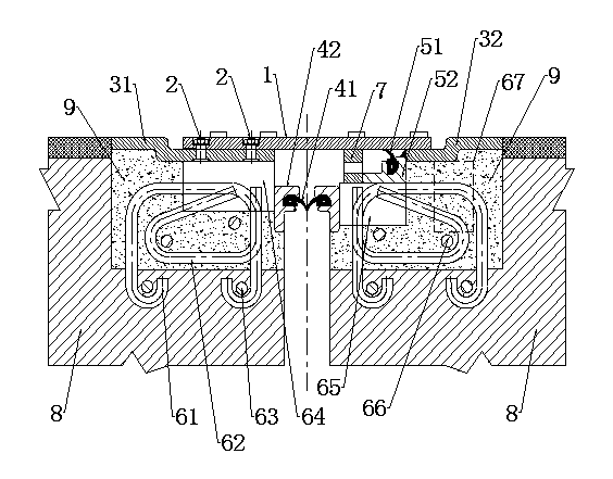
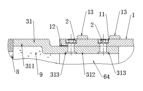
[0038] Such as figure 1 and figure 2 as shown, figure 1 A schematic diagram of the structural principle of a bridge expansion joint device with multiple water-stop structures provide...
PUM
 Abstract
Description
Claims
Application Information