High-strength bolt shear key structure and constructing method thereof

A technology of high-strength bolts and shear keys, which is applied in the direction of building construction, construction, and building materials, can solve problems such as pre-tension relaxation and reduced connection performance of composite structures, and achieve creep reduction and enhanced shear connections Ability and strength, the effect of convenient construction

Inactive Publication Date: 2014-07-16
SOUTHEAST UNIV
View PDF5 Cites 20 Cited by
  • Summary
  • Abstract
  • Description
  • Claims
  • Application Information

AI Technical Summary

Problems solved by technology

At present, the concrete in the shear key of ordinary high-strength bolts directly bears the preload of high-strength bolts. Under local high stress, the creep of co

Method used


Image

  • High-strength bolt shear key structure and constructing method thereof
  • High-strength bolt shear key structure and constructing method thereof
  • High-strength bolt shear key structure and constructing method thereof

Examples


Embodiment 1

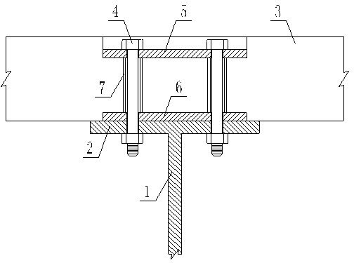
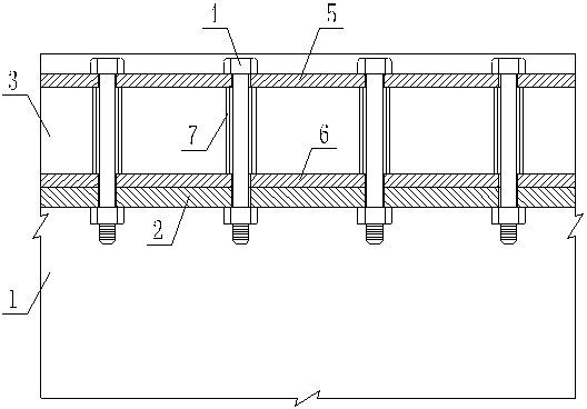
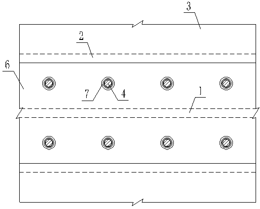
[0014] A high-strength bolt shear key structure, including a steel beam composed of a steel beam web 1 and a steel beam flange 2, a prefabricated concrete slab 3, high-strength bolts 4, and an upper backing plate 5, a lower backing plate 6, and a supporting steel pipe 7 Connectors, the upper and lower ends of the supporting steel pipe 7 are respectively fixed against the upper backing plate 5 and the lower backing plate 6, and the steel beam flange plate 2, the upper backing plate 5 and the lower backing plate 6 are on the axis of the supporting steel pipe 7 All are provided with round holes adapted to the high-strength bolts 4, the inner diameter of the supporting steel pipe 7 is not smaller than the diameter of the above-mentioned round hole, the connecting piece is poured in the precast concrete slab 3, the supporting steel pipe 7 is used as a supporting Most of the high-strength bolts are pre-stressed, so as to reduce the pressure on the concrete, significantly reduce the c...

Embodiment 2

[0017] A construction method for a high-strength bolt shear key structure. Firstly, a steel beam web 1 and a steel beam flange 2 are processed into a steel beam in the form of an I-beam, and a precast concrete slab 3 is manufactured at the same time, and the upper backing plate 5. The connecting piece consisting of the lower backing plate 6 and the supporting steel pipe 7 is poured on the design position of the precast concrete slab, and the supporting steel pipe 7 is sandwiched between the upper backing plate 5 and the lower backing plate 6; then the construction site of the steel beam is completed erection, and then lay the precast concrete slab 3 on the steel beam, and use the supporting steel pipe 7 of the connector as a formwork for drilling; finally, the precast concrete slab 3 and the flange plate 2 of the steel beam are bolted in place until they fit together state, the two are connected by the clamping force of the high-strength bolt 4 .


PUM


Abstract

The invention discloses a high-strength bolt shear key structure and a constructing method of the high-strength bolt shear key structure. The high-strength bolt shear key structure comprises a steel beam composed of steel beam web plates and steel beam flange plates, a precast concrete plate, high-strength bolts and a connecting part formed by an upper cushion plate, a lower cushion plate and a supporting steel pipe, wherein the upper end and the lower end of the supporting steel pipe abut against and are fixed to the upper cushion plate and the lower cushion plate respectively, and the connecting part is cast in the precast concrete plate. The method includes the steps that the steel beam web plates and the steel beam flange plates are manufactured into the I-beam-type steel beam, meanwhile, the precast concrete plate is manufactured, the connecting part formed by the upper cushion plate, the lower cushion plate and the supporting steel pipe are cast in the designed position of the precast concrete plate, and the supporting steel pipe is clamped between the upper cushion plate and the lower cushion plate; the steel beam is paved with the precast concrete plate, and the supporting steel pipe of the connecting part serves as a formwork for hole drilling; the precast concrete plate and the steel beam flange plates are connected through bolts to be in an attached state, and the precast concrete plate and the flange plates can be connected through clamping force of the high-strength bolts.

Description

technical field [0001] The invention relates to a high-strength bolt shear key structure for connecting steel beams and prefabricated concrete slabs and a construction method thereof, belonging to the technical field of civil engineering construction. Background technique [0002] The prefabricated steel-concrete composite structure combines steel beams and prefabricated concrete slabs to work together through shear connectors, which can give full play to the respective advantages of steel and concrete, and is environmentally friendly, convenient for construction, and economical. Advantages, increasingly widely used. [0003] Shear keys are key components in steel-concrete composite structures, and there are many forms. The high-strength bolt shear key connects the precast concrete slab and the flange plate of the steel beam through the clamping force of the high-strength bolt. It has the advantages of easy guarantee of connection quality, quick and convenient constructio...

Claims


Application Information

Patent Timeline
IPC IPC(8): E04B1/38E04B1/41E04G21/00
Inventor 李秉南戴航
Owner SOUTHEAST UNIV
Why Eureka
Try Eureka