
Large plastic plate matching structure based on cantilever buckles

A cantilever buckle and matching structure technology, which is applied in the direction of thin plate connection, connecting components, mechanical equipment, etc., can solve the problems of low support rigidity, poor assembly stability, assembly deformation, etc., to improve support rigidity and shorten flanging Length, effect of reducing the processed surface

Inactive Publication Date: 2014-07-16
BAOSTEEL DEV CO LTD
View PDF7 Cites 29 Cited by
  • Summary
  • Abstract
  • Description
  • Claims
  • Application Information

AI Technical Summary

Problems solved by technology

[0002] Cantilever buckle is a detachable fastener widely used in the matching of plastic parts. It is composed of a buckle on the flange of the cover plate and a groove on the side wall of the base plate. When in use, the flange buckle is directly clamped The lower edge of the flange of the cover plate abuts against the bottom surface of the substrate in a large area, and the flange and the substrate are in oblique contact with a curved surface. Therefore, this method relies on buckling of the flange and the side wall of the substrate and both The assembly method with a large area of ​​contact does not have high support rigidity, and the assembly stability is also poor, which may easily lead to assembly deformation

Method used


Image

  • Large plastic plate matching structure based on cantilever buckles
  • Large plastic plate matching structure based on cantilever buckles
  • Large plastic plate matching structure based on cantilever buckles

Examples


Embodiment Construction

[0028] The present invention will be described in further detail below in conjunction with the accompanying drawings and embodiments. The embodiments are not intended to limit the scope of protection of the invention. Obviously, those skilled in the art can obtain other embodiments without having to pay creative work. Belong to the protection scope of the present invention.

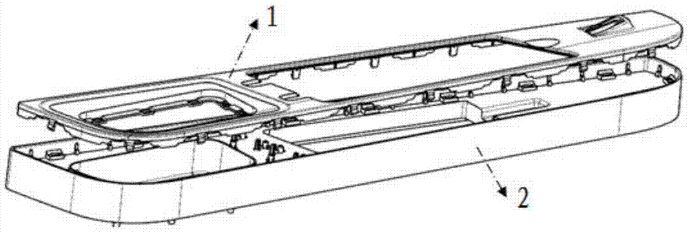
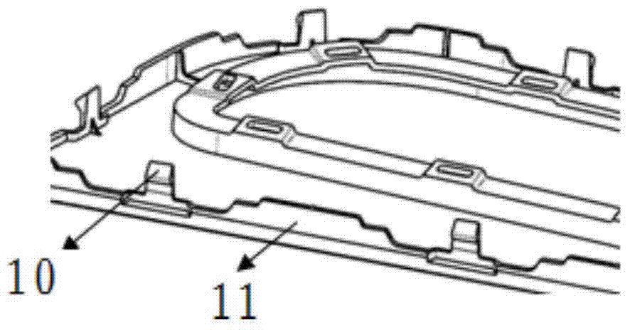
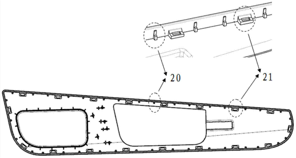
[0029] combine Figure 1 to Figure 7 As shown, a large-scale plastic plate fitting structure based on cantilever buckles includes a cover plate 1 and a base plate 2, and buckles 10 and cover plate flanges 11 are arranged at intervals along the periphery of the cover plate. The inner wall is provided with a card groove boss 21 matched with the buckle and a limit boss 20 for supporting the flanging of the cover plate. When the flanging of the cover plate is folded onto the side wall of the base plate, The lower end surface presses against the top surface of the limiting boss.

[0030] combine Figure 8 w...


PUM


Abstract

The invention relates to a large plastic plate matching structure based on cantilever buckles. The large plastic plate matching structure comprises a cover plate (1) and a basal plate (2), the buckles (10) and cover plate turning edges (11) are arranged on the periphery of the cover plate at intervals, and the inner side wall of the basal plate is provided with clamping groove bosses (21) matched with the buckles and limiting bosses (20) used for supporting the cover plate turning edges. When the cover plate turning edges are turned to the upper portion of the side wall of the basal plate, the lower end faces of the cover plate turning edges abut against the top surfaces of the limiting bosses. Each clamping groove boss comprises a rectangular cavity (210) extending in the Z direction, the top surface of each limiting boss is a vertical limiting surface (201), and circumferential direction limiting surfaces (202) perpendicular to the vertical limiting surfaces are arranged at the upper ends of the vertical limiting surfaces. The limiting bosses are utilized, the clamping groove bosses are matched with the cover plate turning edges, and the buckles are used for multi-point horizontal surface matching; compared with an existing method that cover plate turning edges and grooves in the side wall of the basal plate are directly buckled and the turning edges directly abut against the bottom surface of the basal plate, better assembly stability is achieved.

Description

technical field [0001] The invention relates to a matching structure of plastic products with a conventional cantilever buckle as the basic overlapping form. It can be widely used in the detachable connection of large and medium-sized panels. Background technique [0002] Cantilever buckle is a detachable fastener widely used in the matching of plastic parts. It is composed of a buckle on the flange of the cover plate and a groove on the side wall of the base plate. When in use, the flange buckle is directly clamped The lower edge of the flange of the cover plate abuts against the bottom surface of the substrate in a large area, and the flange and the substrate are in oblique contact with a curved surface. Therefore, this method relies on buckling of the flange and the side wall of the substrate and both The assembly method with large-area contact does not have high support rigidity, and the assembly stability is also poor, which may easily lead to assembly deformation. C...

Claims


Application Information

Patent Timeline
Patent Type & Authority Applications(China)
IPC IPC(8): F16B5/07
Inventor 俞平舟
Owner BAOSTEEL DEV CO LTD
Learn More