Automatic coil binding device and stator coil winding machine with the same installed

A technology of coil device and stator coil, applied in electromechanical devices, manufacturing motor generators, electric components, etc., can solve the problem of insufficient automation and achieve the effect of improving the degree of automation

Inactive Publication Date: 2014-07-16
佛山市顺德区恒日鑫电器有限公司
View PDF6 Cites 7 Cited by
  • Summary
  • Abstract
  • Description
  • Claims
  • Application Information

AI Technical Summary

Problems solved by technology

At present, the commonly used stator coil winding machine only winds the coil on the wire mold electrically, and the wire binding and mold unloading are all manual operations, and the degree of automation is not high enough.

Method used


Image

  • Automatic coil binding device and stator coil winding machine with the same installed
  • Automatic coil binding device and stator coil winding machine with the same installed
  • Automatic coil binding device and stator coil winding machine with the same installed

Examples


Embodiment Construction

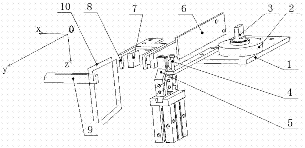
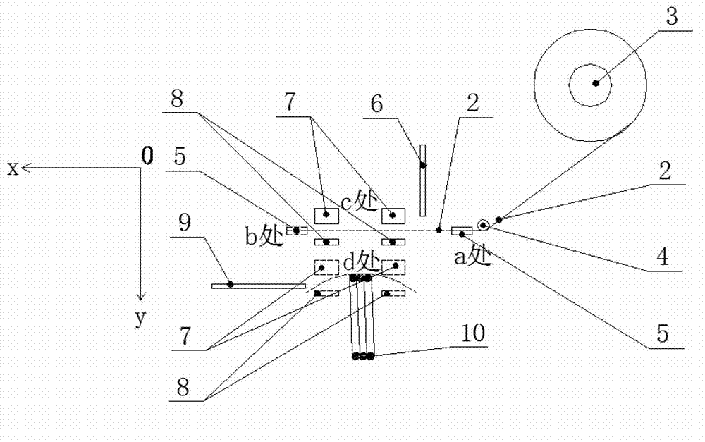
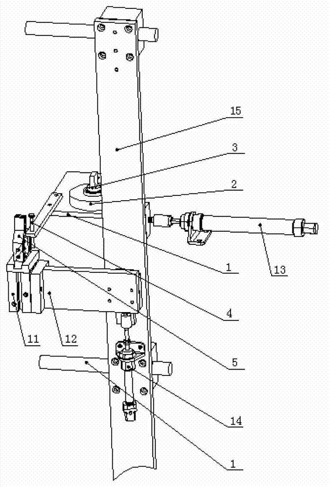
[0028] Figure 3 to Figure 6 It is a structural schematic diagram of the automatic coil binding device of the present invention. It is known from the figure that the automatic coil binding device includes a tape preparation device, a tape cutting device, a tape feeding device and a tape binding device; image 3 As we know, the adhesive tape preparation device includes frame 1, adhesive tape 2, pin shaft 3, guide rod 4, gripper 5, pneumatic gripper 11, upper and lower gripper moving frame 12, left and right cylinders 13, upper and lower cylinders 14 and left and right grippers. Hand mobile frame 15; described bearing pin 3 is fixedly connected on the frame 1, and adhesive plaster 2 is sheathed on the bearing pin 3; Described guide bar 4 is fixedly connected on the frame 1; Described clamping hand 5 is fixed Connected to the moving bar of the pneumatic gripper 11, the pneumatic gripper 11 is fixedly connected to the upper and lower clamping hand moving frame 12; The moving fra...


PUM


Abstract

The invention aims to provide an automatic coil binding device and a stator coil winding machine with the same installed, wherein the stator coil winding machine can automatically complete coil winding, coil binding and coil unloading. The automatic coil binding device comprises an adhesive tape preparing device, an adhesive tape cut-off device, an adhesive tape feeding device and an adhesive tape coil binding device. The stator coil winding machine comprises the automatic coil binding device, and further comprises a baffle, a coil winding device, a coil die advancing and retreating device and a coil clamping and shearing device. A coil die in the coil die advancing and retreating device is arranged within a rotation range of a coil winding rod of the coil winding device. A movable coil clamping block in the coil clamping and shearing device and a fixed coil clamping block in the coil clamping and shearing device are installed above the coil die in the coil die advancing and retreating device and outside the rotation range of the coil winding rod in the coil winding device. The baffle and a coil binding rod in the automatic coil binding device are installed at the position of a notch in the coil die in the coil die advancing and retreating device and directly face a rear adhesive tape feeding clamp in the automatic coil binding device and a front adhesive tape feeding clamp in the automatic coil binding device, the baffle is located on the inner side of the notch, protrudes out to the outer side of the notch and is fixed onto a machine frame, and the coil binding rod is completely located on the inner side of the notch. By means of the automatic coil binding device and the stator coil winding machine, the degree of automation of stator coil winding is greatly increased.

Description

technical field [0001] The invention relates to a stator coil winding machine, in particular to a fully automatic stator coil winding machine. Background technique [0002] The process of stator coil winding is as follows: winding the coil on the wire mold, then binding the wire, and then unloading the mold and going off the wire. At present, the commonly used stator coil winding machine only winds the coil on the wire mold electrically, and the wire binding and mold unloading are all manual operations, and the degree of automation is not high enough. Contents of the invention [0003] The object of the present invention is to provide an automatic coil binding device and a stator coil winding machine equipped with the device to automatically complete winding, binding and unloading. [0004] An automatic coil binding device of the present invention is realized in the following way: the automatic coil binding device includes an adhesive tape preparation device, an adhesive ...

Claims


Application Information

Patent Timeline
Patent Type & Authority Applications(China)
IPC IPC(8): H02K15/00H02K15/08
Inventor 赵华勇
Owner 佛山市顺德区恒日鑫电器有限公司
Why Eureka
Try Eureka