Optical fiber phase compensator and method of use thereof

A phase compensator and fiber coupler technology, which is used in fiber transmission, eliminating distortion/dispersion, etc., and can solve problems such as reducing system performance and exceeding the tolerance of optical path jitter error.

Active Publication Date: 2016-08-24
中国电子科技集団公司第三十四研究所 +2
View PDF4 Cites 0 Cited by
  • Summary
  • Abstract
  • Description
  • Claims
  • Application Information

AI Technical Summary

Problems solved by technology

Special optical signal transmission systems such as optical fiber timing system and phase-correlated high-speed optical fiber radio frequency signal transmission (ROF) system have very high requirements on the accuracy of the optical path. The influence of ambient temperature and vibration on the optical fiber often makes the optical path jitter error of the system greatly exceed the tolerance. , seriously reducing the performance of the system
However, long-distance optical fibers cannot avoid the influence of ambient temperature and vibration. When the existing phase-correlated high-speed optical fiber radio frequency signal transmission (ROF) system transmits 10GHz carrier signals, it must satisfy the condition that the phase deviation is less than 5°, and the transmission distance is less than 50 meters.

Method used


Image

  • Optical fiber phase compensator and method of use thereof
  • Optical fiber phase compensator and method of use thereof
  • Optical fiber phase compensator and method of use thereof

Examples


Embodiment 1

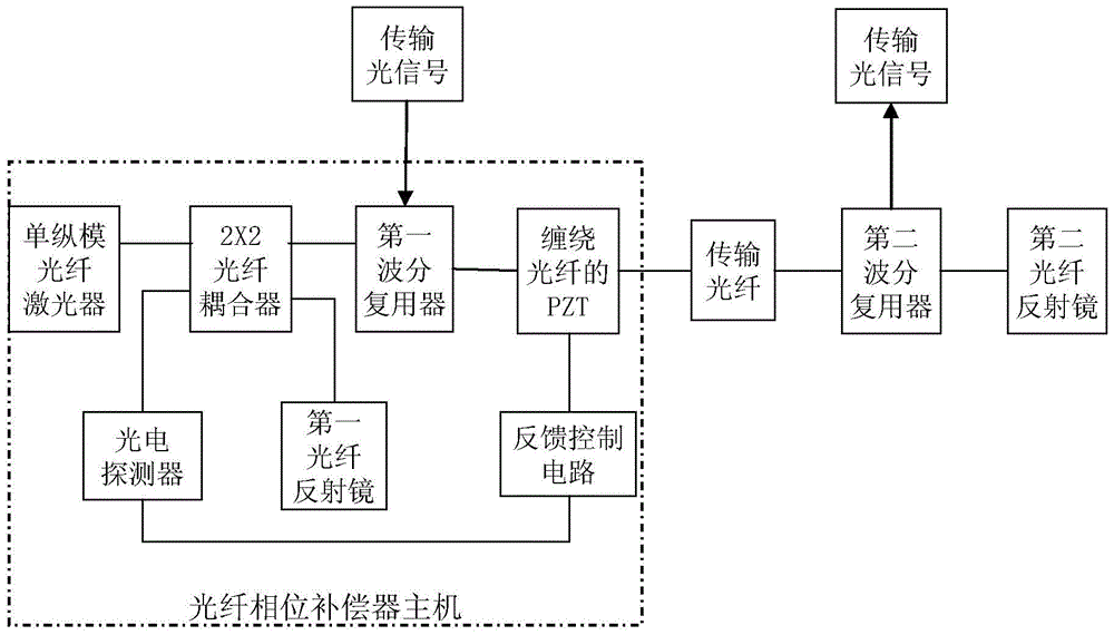
[0030] Fiber phase compensator using Michelson interferometer.

[0031] The embodiment of this optical fiber phase compensator is for example figure 1As shown, it includes a single longitudinal mode laser, a fiber coupler, a fiber interferometer, piezoelectric ceramics, a transmission fiber and a feedback control circuit, and the transmission fiber is a single-mode fiber. A first wavelength division multiplexer and a second wavelength division multiplexer are arranged at both ends of the transmission fiber. The laser output by the single longitudinal mode laser is a continuous laser with stable power, its wavelength is different from that of the transmission optical signal, and the coherence length in the transmission fiber is at least twice the length of the transmission fiber. The laser light emitted by the single longitudinal mode laser is connected to the first port of the 2×2 fiber coupler and divided into the same two beams, and one beam of laser light output from the s...

Embodiment 2

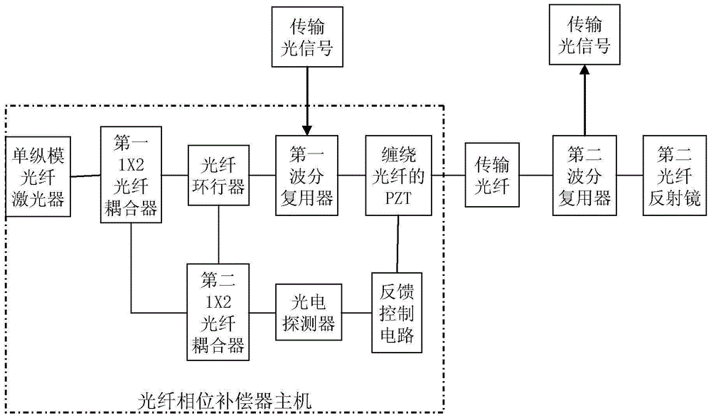
[0048] Fiber phase compensator using Mach-Zehnder interferometer.

[0049] The embodiment of this optical fiber phase compensator is for example image 3 As shown, replace the 2×2 fiber coupler and the first fiber mirror of embodiment 1 with 2 1×2 fiber couplers and fiber circulators to form a Mach-Zehnder fiber interferometer, and other structures are the same as those of embodiment 1 Similar to the optical fiber phase compensator, the laser emitted by its single longitudinal mode laser is connected to the first 1×2 fiber coupler and divided into two beams, one of which is input to the transmission end of the first wavelength division multiplexer through the optical fiber circulator; The other laser beam is connected to an input port of the second 1×2 fiber coupler as a local single longitudinal mode laser signal; the single longitudinal mode laser signal returned from the other end of the transmission fiber enters the second 1×2 fiber coupler through the fiber circulator Th...


PUM


Abstract

The invention provides an optical fiber phase compensator and a use method of the optical fiber phase compensator. A laser of a single longitudinal mode laser device of the optical fiber phase compensator is divided into two beams through an optical fiber coupler, one beam is input into a first wavelength division multiplexer and transmitted to a transmission optical fiber along with a transmission optical signal, one end of the transmission optical fiber is wound around piezoelectric ceramics (PZT), the other end of the transmission optical fiber is connected with a second wavelength division multiplexer, an output single longitudinal mode laser signal is reflected by a second optical fiber reflecting mirror and returned through the transmission optical fiber, interference between the optical fiber coupler and the local single longitudinal model laser signal is generated, an interference optical signal enters a feedback control circuit, a control signal controls the PZT flexible range, an upper optical fiber optical path of the PZT is changed, and phase compensation is conducted on the transmission optical signal. The use method comprises the steps that a stable phase point of the optical fiber phase compensator is firstly set and automatic phase compensation is conducted by the PZT; when the adjustment limitation of the PZT is reached, reset is conducted. The stable phase transmission distance of one-level compensation reaches 25 km and a cascade optical fiber phase compensator can be formed through multiple levels.

Description

technical field [0001] The invention relates to the technical field of optical fiber communication, in particular to an optical fiber phase compensator and a method for using the same, so as to accurately compensate the jitter error caused by the optical path change of the transmitted optical signal. Background technique [0002] Affected by changes in ambient temperature, single-mode optical fibers will experience thermal expansion and contraction as well as changes in the refractive index. Vibrations in the environment will also cause small changes in the refractive index of the optical fiber. Changes in these environmental factors will cause the transmission of optical signals in the optical fiber The optical path changes and jitter occurs. Special optical signal transmission systems such as optical fiber timing system and phase-correlated high-speed optical fiber radio frequency signal transmission (ROF) system have very high requirements on the accuracy of the optical p...

Claims


Application Information

Patent Timeline
Patent Type & Authority Patents(China)
IPC IPC(8): H04B10/25H04B10/2507
Inventor 岳耀笠刘志强覃波吴国锋阳华李恩欧阳竑吕宏伟张昕童章伟
Owner 中国电子科技集団公司第三十四研究所
Why Eureka
Try Eureka