Sand discharge device and sand discharge method for ballast tank

A ballast tank and pump device technology, which is applied to the pipelines for emptying/ballasting, cleaning equipment for ship tanks, transportation and packaging, etc., can solve the problems of low efficiency, labor-consuming, time and cost difficulties, etc.

Inactive Publication Date: 2014-07-16
JFEENG CORP +1
View PDF7 Cites 11 Cited by
  • Summary
  • Abstract
  • Description
  • Claims
  • Application Information

AI Technical Summary

Problems solved by technology

In this way, it is a labor-intensive, time-consuming, and cost-intensive task to remove sand and sand from a large number of longitudinal bone grooves for each longitudinal bone groove, and it is a very low-efficiency operation.

Method used


Image

  • Sand discharge device and sand discharge method for ballast tank
  • Sand discharge device and sand discharge method for ballast tank
  • Sand discharge device and sand discharge method for ballast tank

Examples


no. 1 approach

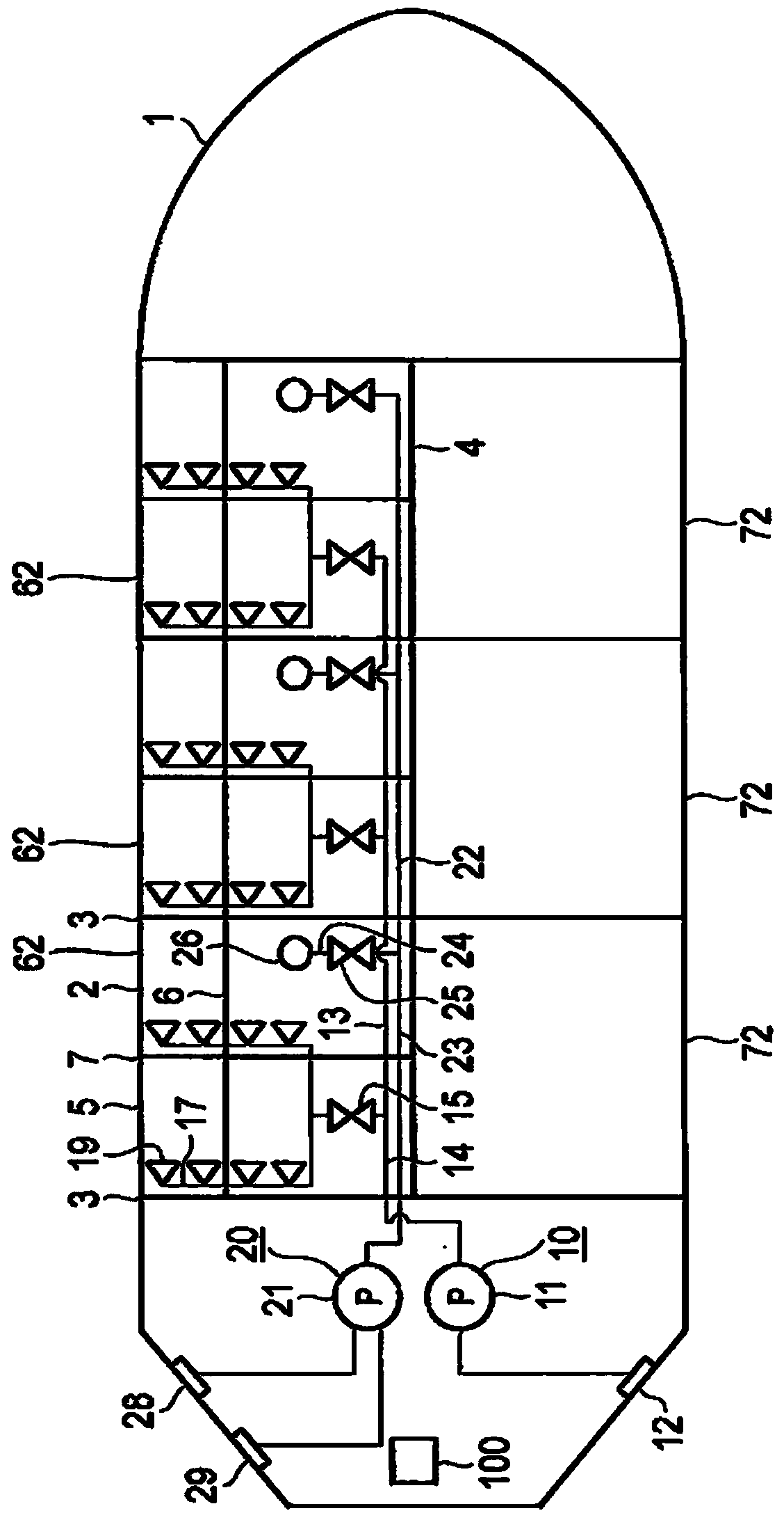
[0065] figure 1 It is a horizontal cross-sectional view showing the sand discharge device installed in the ballast tank 2 of the ship 1 as the first embodiment of the present invention.

[0066] On the ship 1 there are three ballast tanks 2 each along the length of the ship on the port side and on the starboard side. The ballast tank 2 has a port side ballast tank 62 and a starboard side ballast tank 72 . In addition, in figure 1 In , the device structure of the sand discharge device of the port ballast tank 62 is shown, and the device structure of the sand discharge device of the starboard side ballast tank 72 is omitted.

[0067] The ballast tanks 2 become closed spaces, and the closed spaces are surrounded by hull side plates, hull bottom plates, transverse bulkheads and longitudinal bulkheads between adjacent ballast tanks 2 . The internal space of the ballast tank 2 is divided into a plurality of compartments 5 by girders (longitudinal penetrating partitions) 6 and rib...

no. 2 approach

[0102] In the second embodiment, the means for spraying water from the nozzles and the means for discharging muddy water from the water injection port are the same as those in the first embodiment, and description thereof will be omitted.

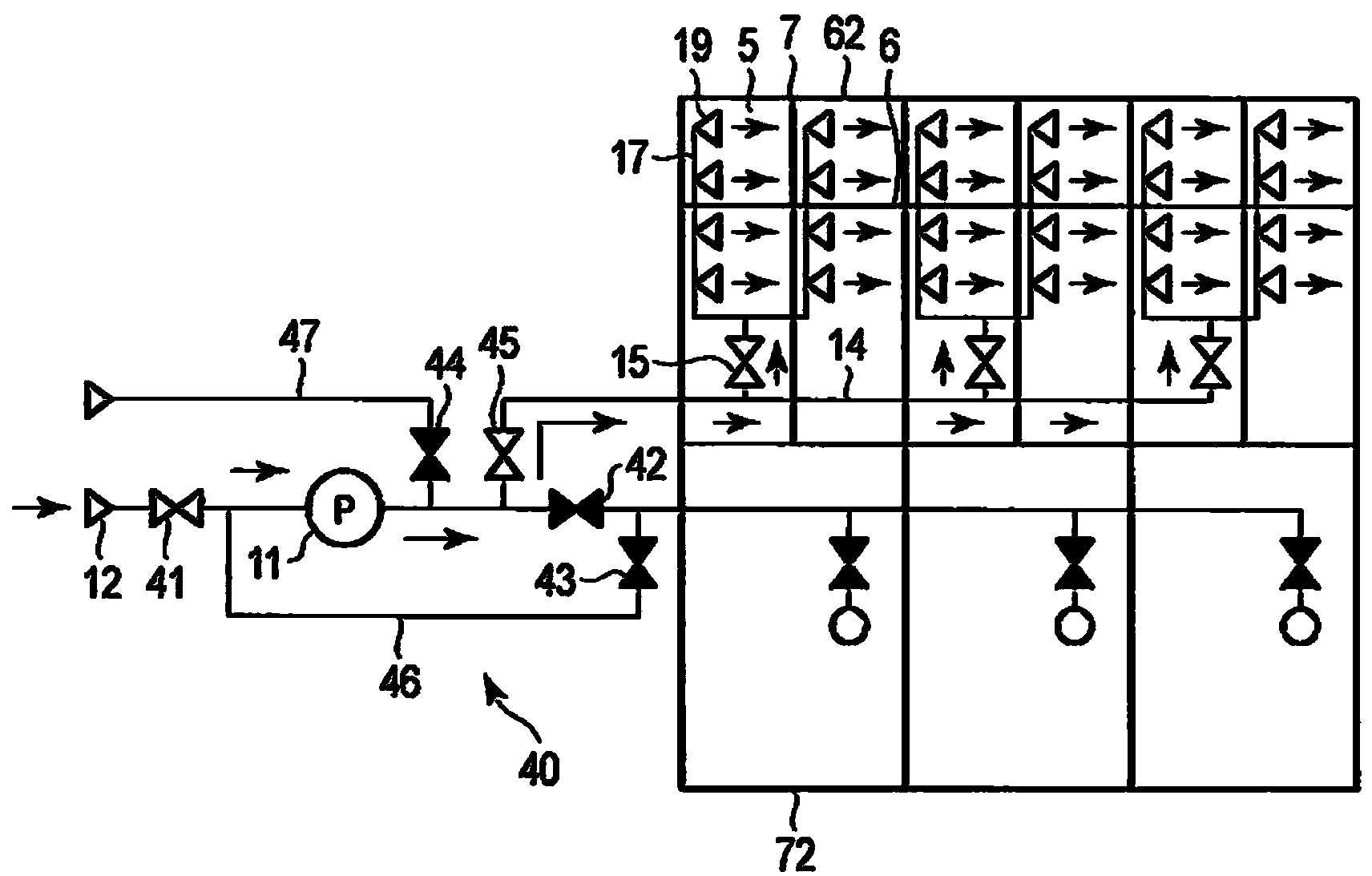
[0103] Figure 6 is a sectional oblique view showing a compartment which is part of a ballast tank formed on the bottom of the ship, Figure 7A yes Figure 6 Sectional views of the compartments in the section extending along the length of the ship, and, Figure 7B yes Figure 6 The sectional view of the compartment extending along the ship's width direction.

[0104] The hull is formed as a double bottom, from Figure 6 It can be seen that there is a bottom plate 8 and an upper bottom plate 9 between which a ballast tank is formed. The internal space of the ballast tank is divided into a plurality of compartments 5 by girders (longitudinal penetrating partitions) 6 and ribs (horizontal plates) 7. The girders 6 extend along the length o...

no. 3 approach

[0123] In the third embodiment, the means for spraying water from the nozzles and the means for discharging muddy water from the injection water outlet are the same as those in the first embodiment, and description thereof will be omitted.

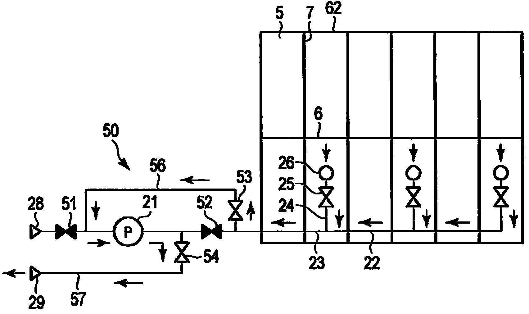
[0124] Figure 9 is a sectional oblique view showing a compartment which is part of a ballast tank formed on the bottom of the ship, Figure 10A yes Figure 9 Sectional views of the compartments in the section extending along the length of the ship, and, Figure 10B yes Figure 9 The sectional view of the compartment extending along the ship's width direction.

[0125] The hull is formed as a double bottom, from Figure 9 It can be seen that there is a bottom plate 8 and an upper bottom plate 9 between which a ballast tank is formed. The internal space of the ballast tank is divided into a plurality of compartments 5 by girders (longitudinal penetrating partitions) 6 and ribs (horizontal plates) 7. The girders 6 extend along the lengt...


PUM


Abstract

A sand discharge device, which discharges mud and sand deposited in ballast tanks (2) comprising multiple tank compartments (5) in a ship (1) equipped with a port-side water injection/drainage pump (21) and a starboard-side water injection/drainage pump (11), which inject water into and drain water from the ballast tanks (2), wherein this sand discharge device is equipped with: nozzles (19) which are provided near the tank floor plate (8) of the tank compartments (5), and which spray water; a water feed pipeline (13) that feeds water to the nozzles (19); a water discharge pipeline (22) that discharges from the ballast tanks (2) muddy water in which mud and sand that has been washed away by the water sprayed from the nozzles (19) has been dispersed and suspended; and a water feed/discharge control means (100) which, when mud and sand is discharged from the port-side ballast tanks (2), opens/closes a valve in the water feed pipeline (13) and operates the starboard-side water injection/drainage pump (11) so as to feed water into the port-side water feed pipeline (13) from the starboard-side water injection/drainage pump (11), and opens/closes a valve in the water discharge pipeline (22) and operates the port-side water injection/drainage pump (21) so as to discharge muddy water from the port-side water discharge pipeline (22) by means of the port-side water injection/drainage pump (21). Thus, the mud and sand accumulated in the ballast tanks (2) can be discharged efficiently.

Description

technical field [0001] The invention relates to a sand discharge device and a sand discharge method of a ballast tank, which discharges the sand accumulated in the ballast tank of a ship. Background technique [0002] Seawater or river water is injected into the ballast tank of a ship. However, if seawater or river water is sucked in by a pump in a port with a shallow draft, the seawater or river water mixed with silt will be injected into the ballast tank. In addition, river water with suspended and dispersed fine particles of mud is sometimes injected into the ballast tank. When such water mixed with silt is poured into the ballast tank, silt will settle and accumulate on the bilge during the voyage of the ship. [0003] Even if the ballast water is discharged, it is difficult to flow out the accumulated silt and the accumulated sediment remains in the ballast tank in many cases. In this way, if the silt is still accumulated in the ballast tank, the loading capacity of t...

Claims


Application Information

Patent Timeline
Patent Type & Authority Applications(China)
IPC IPC(8): B63B13/00B63B57/02
CPCB63B57/02
Inventor 长藤雅则冈本幸彦山田久行
Owner JFEENG CORP
Why Eureka
Try Eureka