Working platform for offshore wind energy plant and method for manufacturing same

A technology for working platforms and wind energy devices, applied in wind power generation, manufacturing tools, engine manufacturing, etc., can solve problems such as anti-corrosion, high maintenance costs, cost and time consumption in complex assembly work of working platforms, and achieve flexible design or structure, The effect of cost saving and flexible production

Active Publication Date: 2014-07-16
AREVA WIND
View PDF5 Cites 8 Cited by
  • Summary
  • Abstract
  • Description
  • Claims
  • Application Information

AI Technical Summary

Problems solved by technology

This can lead to high repair costs
[0005] In addition, the large number of individual components not only leads to complex assembly work of the work platform but also requires anti-corrosion treatment of each component
Corrosion protection of a large number of individual components is a cost and time consuming process

Method used


Image

  • Working platform for offshore wind energy plant and method for manufacturing same
  • Working platform for offshore wind energy plant and method for manufacturing same
  • Working platform for offshore wind energy plant and method for manufacturing same

Examples


Embodiment Construction

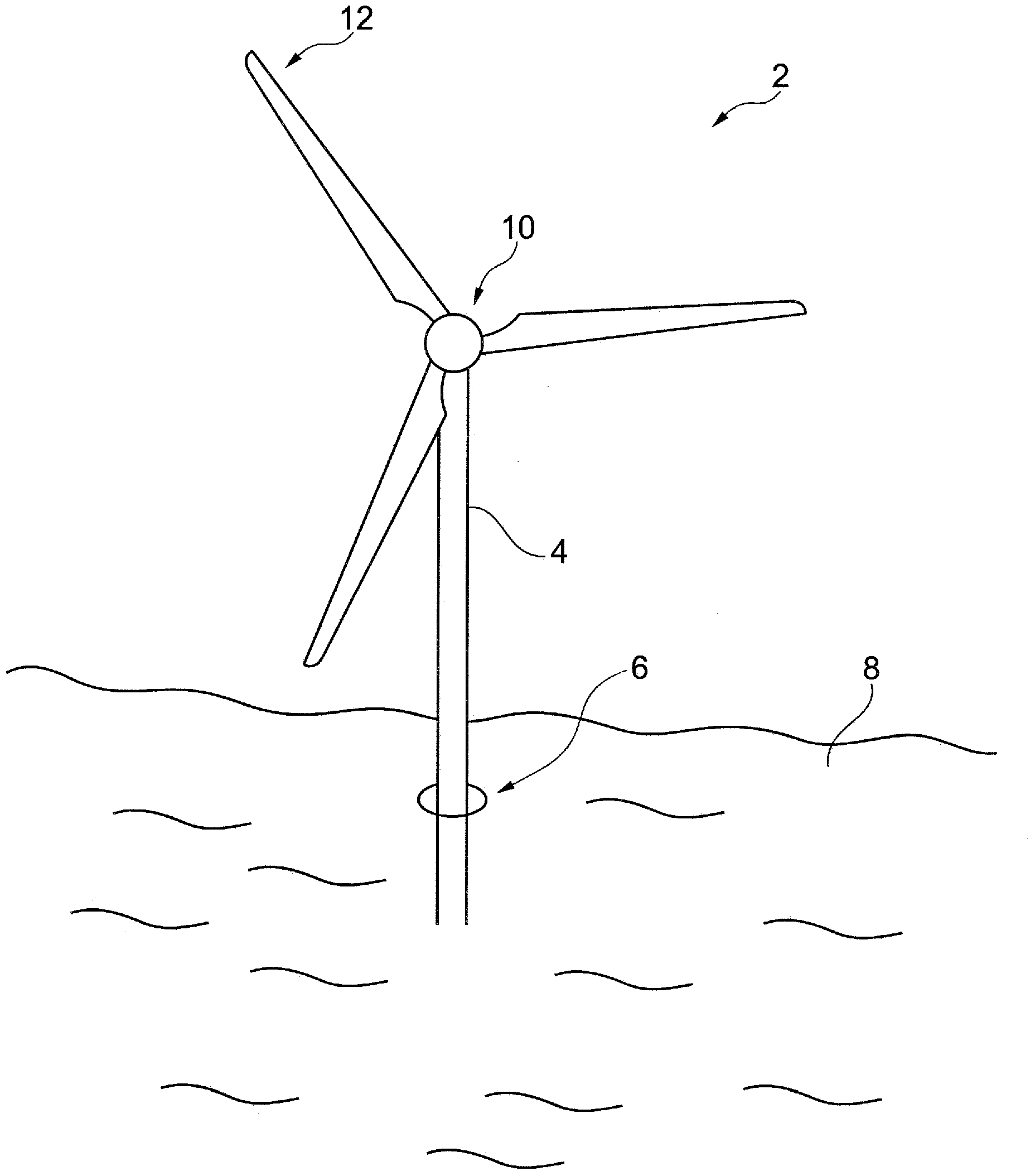
[0037] figure 1 It is a simplified offshore wind energy installation 2 with a tower 4 and a working platform 6 . The tower 4 is built on a suitable submerged foundation in the sea 8 and carries a hub 10 which itself carries the rotor blades 12 . During erection of the tower 4, several tower segments are assembled offshore.

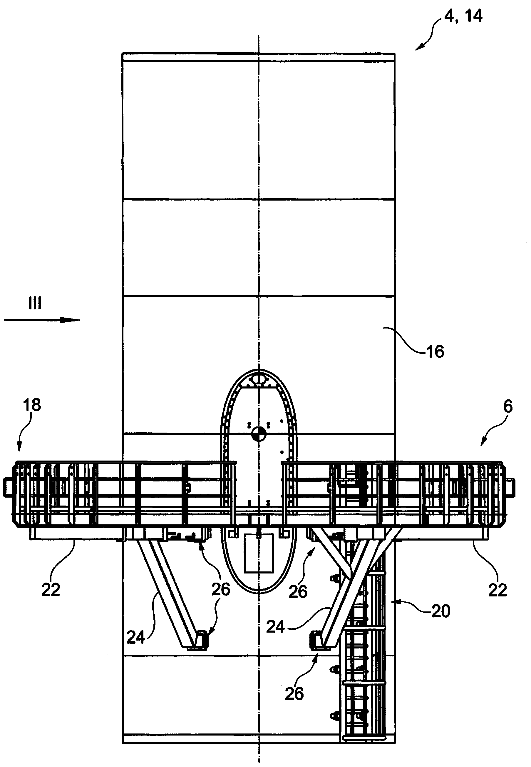
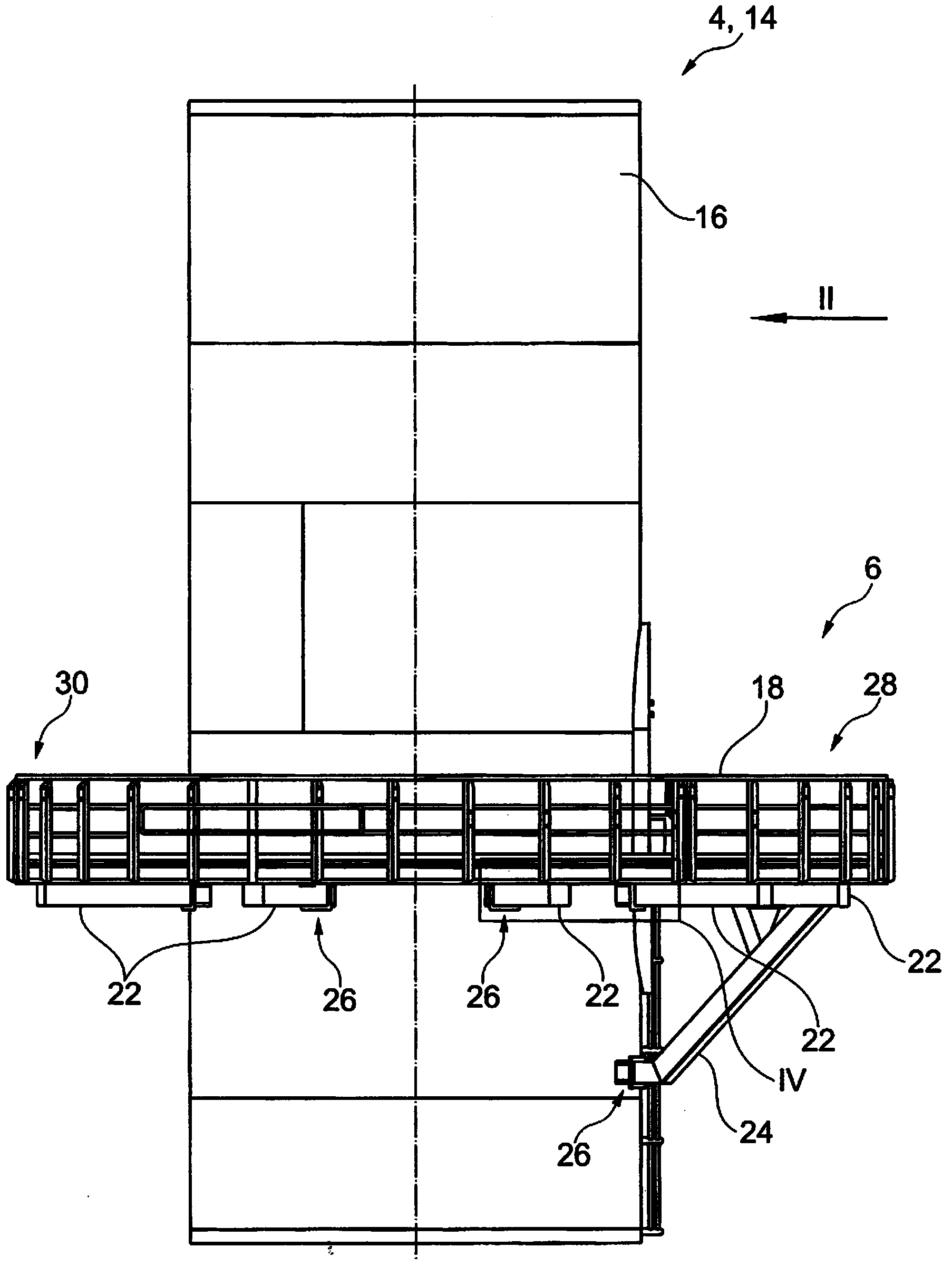
[0038] figure 2 There is shown a tower segment 14 and a working platform 6 welded to the tower 4 and the outer wall 16 of the tower segment 14 respectively. The work platform 6 includes a safety handrail 18 surrounding the work platform 6 at its periphery. The working platform 6 is accessible via an ascending ladder 20 which is also welded to the wall 16 of the tower segment 14 . The service engineer can access the wind energy installation 2 via the working platform 6 using the ascending ladder 20 . The working platform 6 is fixed to the tower segment 14 via radial beams 22 which are part of the load-bearing structure of the working platform 6 . For...


PUM


Abstract

Working platform (6) and offshore wind energy plant (2) comprising a working platform (6), wherein the working platform (6) is configured to be mounted to an outside wall (16) of the tower (4) of the offshore wind energy plant (2) by help of welded joints.

Description

technical field [0001] The invention relates to a working platform for an offshore wind energy device and an offshore wind energy device with the working platform. Further, the invention relates to a method of manufacturing an offshore wind energy installation. Background technique [0002] Typically, the working platforms of offshore wind energy installations are multipurpose units. Primarily, work platforms eg provide service engineers with access to wind energy installations and allow receiving service equipment or spare parts for wind energy installations eg from supply ships, today's work platforms use an extremely large number of individual components and hundreds of studs and screw connection. For example, a typical work platform according to the prior art has around 700 screw connections. Each screw and stud must be inserted (ie hammered in) and then tightened following intricate shop drawings. Further, screw connections have to be checked and re-torqued followin...

Claims


Application Information

Patent Timeline
Patent Type & Authority Applications(China)
IPC IPC(8): E04G7/30F03D1/00F03D11/04E04G3/24
CPCF03D13/10F03D13/25F03D80/50F05B2230/232F05B2230/61F05B2240/911F05B2240/95Y02E10/72Y02E10/727Y02P70/50B23K31/02E02B17/0004E02B17/0026E02B17/027E02B2017/0056E02B2017/0065E04H12/34Y02E10/728
Inventor 托马斯·克拉梅尔米夏埃尔·根里希
Owner AREVA WIND
Why Eureka
Try Eureka