
Code printing system, method and device

A coding lens and position information technology, applied in the field of coding systems, can solve the problems of ID code deviation from the coding position frame, poor coding accuracy and coding process stability, economic losses of manufacturers, etc., to improve stability, monitor The effect of reducing management difficulty and improving stability

Active Publication Date: 2014-07-23
BOE TECH GRP CO LTD +1
View PDF12 Cites 10 Cited by
  • Summary
  • Abstract
  • Description
  • Claims
  • Application Information

AI Technical Summary

Problems solved by technology

Using the existing technology to code the ID code often causes the ID code to deviate from the coding position frame, and some ID codes may even be formed outside the coding position frame. The coding accuracy and the stability of the coding process are poor. Unqualified may lead to the inability to read the ID code, which is not only not conducive to the follow-up investigation of the product, but also brings huge economic losses to the manufacturer

Method used


Image

  • Code printing system, method and device
  • Code printing system, method and device
  • Code printing system, method and device

Examples


Embodiment Construction

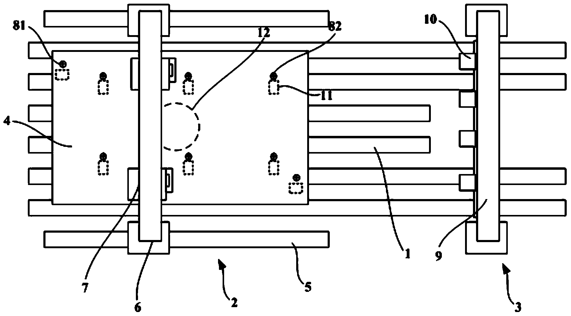
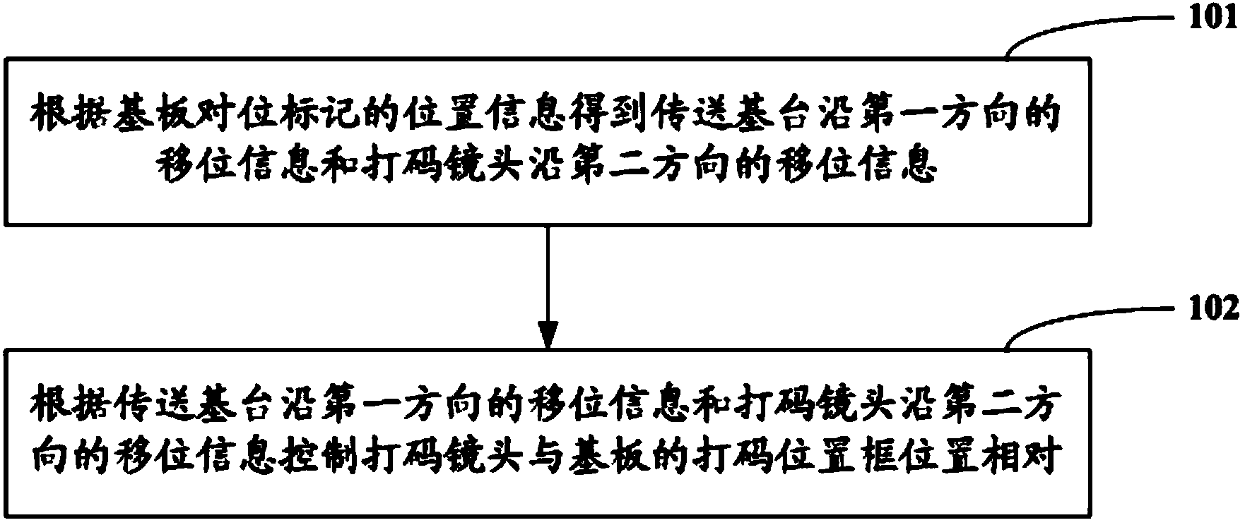
[0036] In order to improve the coding accuracy and the stability of the coding process, and reduce the difficulty of product monitoring and management, the embodiments of the present invention provide a coding system, method and device. In the technical solution of the present invention, the alignment lens collects the position information of the substrate alignment mark, and the control device obtains the displacement information of the transmission base along the first direction and the displacement information of the coding lens along the second direction according to the position information of the substrate alignment mark. Shift information; according to the shift information of the transmission base station along the first direction and the shift information of the coding lens along the second direction, the position of the coding lens is controlled relative to the coding position frame of the substrate. Compared with the prior art, the marking The code position is determ...


PUM


Abstract

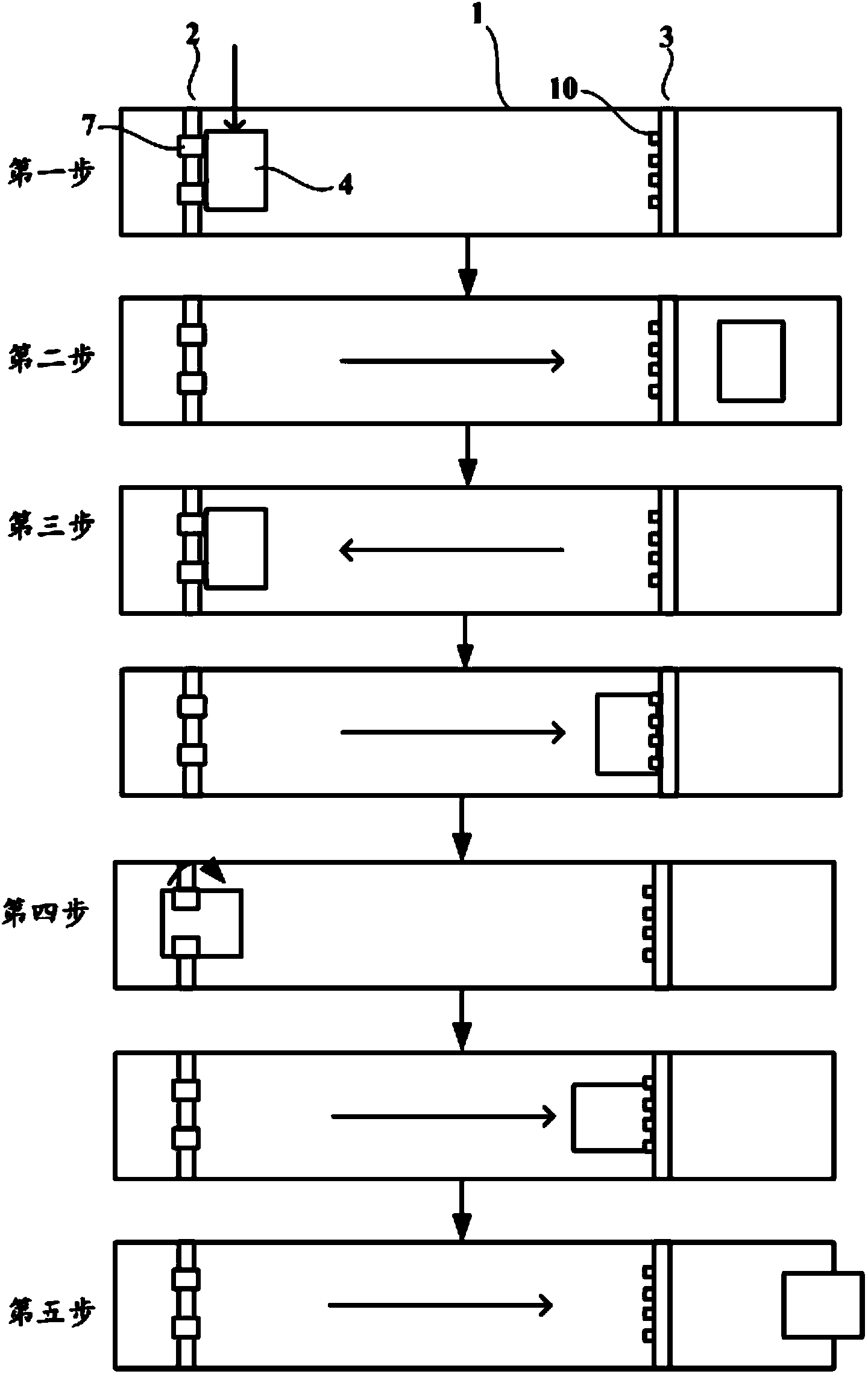
The invention relates to the technical field of displaying, and discloses a code printing system, method and device. The code printing system, method and device are used for improving code printing precision and stability of the code printing process and lowering the monitor management difficulty of products. The code printing system comprises a conveying base station for conveying a base plate in the first direction, alignment equipment, code printing equipment and control equipment. The alignment equipment comprises an alignment guide rail arranged in the first direction, a drive rod and an alignment camera lens, the drive rod is assembled on the alignment guide rail in a sliding mode and is arranged in the second direction, and the alignment camera lens is assembled on the drive rod in a sliding mode and used for collecting position information of alignment marks of the base plate. The code printing equipment comprises a supporting rod parallel to the drive rod and a code printing camera lens assembled on the supporting rod in a sliding mode. The control equipment is respectively in signal connection with the conveying base station, the alignment camera lens and the code printing camera lens and is used for obtaining the displacement information of the conveying base station in the first direction and the displacement information of the code printing camera lens in the second direction according to the position information of the alignment marks of the base plate, and the code printing camera lens and a code printing position frame of the base plate are controlled to be opposite in position.

Description

technical field [0001] The invention relates to the field of display technology, in particular to a coding system, method and device. Background technique [0002] At present, in the manufacturing industry of TFT-LCD (Thin Film Transistor Liquid Crystal Display, TFT-LCD for short) and OLED (Organic Light Emitting Diode, OLED for short), in order to continuously improve product yield And conduct follow-up investigations on defective products. Each panel has a unique ID code, and the glass substrate that makes the panel also has a unique ID code. [0003] ID code coding is usually carried out in the initial stage of the array substrate manufacturing process. First, the ID code coding position frame (ID Pad) is formed on the substrate through the exposure process, and then the substrate is aligned, and the coding machine prints the code according to the stored The position information scans and exposes the substrate to form an ID code in the coding position frame. The coding ...

Claims


Application Information

Patent Timeline
Patent Type & Authority Applications(China)
IPC IPC(8): B41J3/407B41J29/38
Inventor 黄敬义许朝钦金基用罗丽平
Owner BOE TECH GRP CO LTD
Learn More