Energy-saving vehicle

An energy-saving vehicle and vehicle body technology, applied in the field of vehicles, can solve the problems of heavy pollution, consumption of other energy sources or external charging, and inability to drive with self-sufficient power generation, and achieve the effect of increasing volume and power generation

Active Publication Date: 2014-07-23
陈璐瑶
View PDF8 Cites 9 Cited by
  • Summary
  • Abstract
  • Description
  • Claims
  • Application Information

AI Technical Summary

Problems solved by technology

[0003] The purpose of the present invention is to provide an energy-saving vehicle, which solves the technical problems that existing vehic

Method used


Image

  • Energy-saving vehicle
  • Energy-saving vehicle
  • Energy-saving vehicle

Examples


specific Embodiment 1

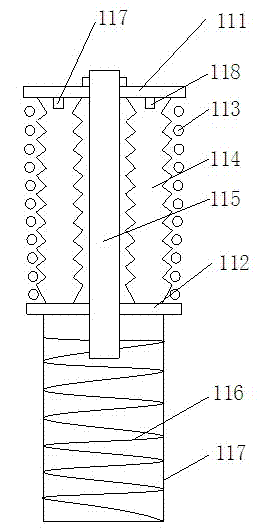
[0035] This embodiment proposes an energy-saving vehicle. The energy-saving vehicle includes a vehicle body, a suspension system located between the vehicle body and the wheels, and the suspension system is provided with a vibration reduction power generation device. There will be relative movement between the front and rear wheel suspensions. At this time, the vibration reduction power generation device of the energy-saving vehicle realizes the vibration reduction function.

[0036] Such as figure 1 As shown, the vibration-damping power generation device of the present embodiment comprises a vibration-damping upper seat 111, a vibration-damping lower seat 112, a vibration-damping spring 113, a vibration-damping airbag 114, a magnetic rod 115, and a generator coil 116; the bottom of the vibration-damping lower seat 112 is provided with Housing 117, housing 117 inside is provided with generator coil 116; one end of magnetic rod 115 is installed on the vibration-damping upper se...

specific Embodiment 2

[0060] The difference between this embodiment and specific embodiment 1 lies in that the structure of the linear generator of this embodiment is different from that of specific embodiment 1, and the rest of the implementation methods are the same, which will not be repeated here.

[0061] Such as Figure 9 As shown, the two ends of the housing 51 of the linear generator in this embodiment are respectively fixed with magnets 55 that repel the polarities of the magnets 53 . Through the repulsive force of the magnets 55 fixed at both ends of the housing 51, the sliding of the magnets 53 is accelerated, thereby increasing the power generation.


PUM


Abstract

The invention relates to an energy-saving vehicle which comprises a suspension system. The suspension system is provided with a vibration reduction power generation device which comprises a vibration reduction upper seat, a vibration reduction lower seat, a vibration reduction spring, a vibration reduction air bag, a magnetic bar and a power generation coil. The lower portion of the vibration reduction lower seat is provided with a shell, and the power generation coil is arranged in the shell. One end of the magnetic bar is installed on the vibration reduction upper seat, and the other end of the magnetic bar penetrates through the vibration reduction lower seat and extends into the shell. The vibration reduction air bag is cylindrical and is located between the vibration reduction upper seat and the vibration reduction lower seat and arranged on the magnetic bar in a sleeved mode. The vibration reduction air bag is provided with an air inlet and an air outlet, and turbine generators are arranged in the air inlet and the air outlet. The vibration reduction spring is fixedly arranged between the vibration reduction upper seat and the vibration reduction lower seat and arranged on the vibration reduction air bag in a sleeved mode. In addition, the energy-saving vehicle is further provided with a linear generator and a vibration generator. The energy-saving vehicle can drive the vibration reduction power generation device, the linear generator, the vibration generator and the turbine generators to generate power.

Description

technical field [0001] The invention belongs to the technical field of vehicles, and in particular relates to an energy-saving vehicle capable of self-sufficient power generation. Background technique [0002] With the depletion of global energy, people pay more and more attention to energy conservation and environmental protection. Existing automobiles need to use various fuel gas or external electric energy to provide power for the vehicle, which consumes a large amount of energy that is decreasing day by day, and at the same time causes huge pollution, and the cost of manufacture, use, and maintenance is very high, which is inconvenient. Contents of the invention [0003] The object of the present invention is to provide an energy-saving vehicle, which solves the technical problems that the existing vehicles need to consume other energy sources or external charging, cause heavy pollution, and cannot run with self-sufficient power generation. In order to solve the above...

Claims


Application Information

Patent Timeline
IPC IPC(8): B60G13/14B60L8/00
CPCY02T10/7072
Inventor 陈璐瑶
Owner 陈璐瑶
Why Eureka
Try Eureka