Traveling vehicle power supply device

A technology of power supply device and power supply components, which is applied in the direction of power rails, etc., can solve the problems of less stored energy and long charging time, and achieve the effects of smooth driving, environmental protection, and reduction of exhaust emissions

Active Publication Date: 2014-07-23
福州开发区和世林实业发展有限公司
View PDF6 Cites 24 Cited by
  • Summary
  • Abstract
  • Description
  • Claims
  • Application Information

AI Technical Summary

Benefits of technology

This new technology allows cars to charge their batteries while they drive by directly providing electricity from sunlight instead of relying solely upon fuel combusted within them themselves. Additionally, this system uses clean sources like water to generate hydrogen gas that powers up an engine when needed, eliminates any harmful chemicals released overtime. Overall, these technical improvements improve efficiency and reduce pollution caused by traditional methods used at home (fuel).

Problems solved by technology

This patented technical problem addressed by this patents describes how current battery technology cannot store more than 100 kilowatt hours (kWh) of electrical capacity without causing environmental concerns or requiring expensive maintenance due to their high cost compared with traditional fossil fuel cars.

Method used


Image

  • Traveling vehicle power supply device
  • Traveling vehicle power supply device
  • Traveling vehicle power supply device

Examples


Embodiment 1

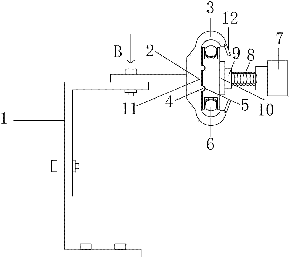
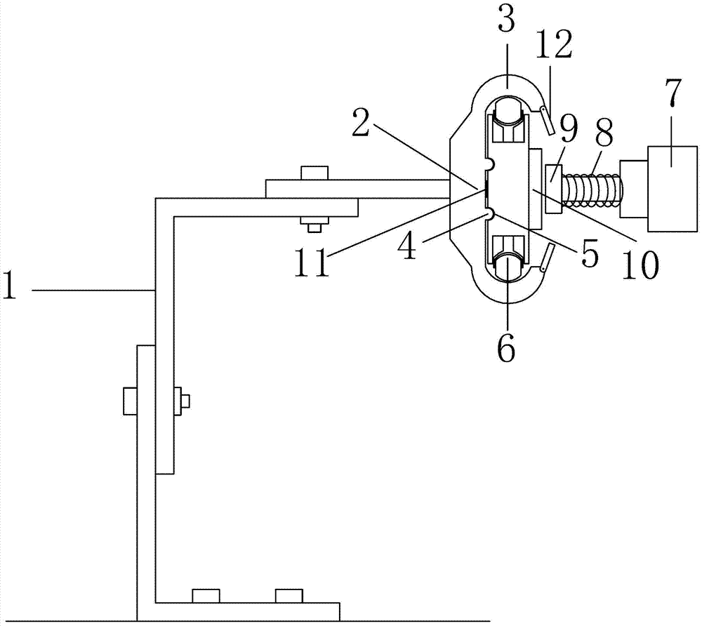
[0023] Such as Figure 1 to Figure 8 Shown is a schematic diagram of an embodiment of a driving power supply device provided by the present invention.

[0024] A power supply device for driving, suitable for hybrid electric vehicles, it includes a power supply assembly arranged on the driveway and a connector connected to the vehicle for power supply through wires. The power transmission guide rail 4 extending from the driveway and connected to the power supply, the connector is provided with a conductive interface 5 that cooperates with the power transmission guide rail 4, and the two sides of the connector are provided with sliding parts that can be stretched or opened to the outside of the connector and cooperate with the sliding track 6. The sliding member 6 is a pulley that can be stretched or expanded to both sides.

[0025] Because highways are mostly straight roads, there are no crossroads, and there is less interference, it is especially suitable for the application ...

Embodiment 2

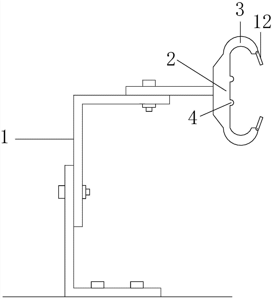
[0038] Such as Figure 9 to Figure 11 Shown is a schematic diagram of an embodiment of another driving power supply device provided by the present invention.

[0039] The difference between this embodiment and embodiment 1 is that in embodiment 1, the slider 6 is opened to both sides and against the slideway 3, so that the connector is slidably connected to the power supply assembly, while in embodiment 2, the connector is slid by sliding The part 6 shrinks toward the middle, and clamps the slideway 3, so that the connector is slidably connected to the power supply assembly.

[0040] Such as Figure 9 The sliding track includes a support plate 2 and two slideways 3 that are separately arranged at both ends of the support plate 2, and the track surface for the sliding part 6 to slide is arranged on the outside, and the track surface can be a convex or concave arc surface, There is a gap for accommodating the connecting head between the two slideways 3 .

[0041]The two sides...


PUM


Abstract

The invention relates to a traveling vehicle power supply device. The traveling vehicle power supply device comprises a power supply assembly and a connector, wherein the power supply assembly is arranged on a lane, and the connector is connected with a vehicle through a wire to supply power. The power supply assembly comprises a sliding rail and a power transmission guide rail, wherein the sliding rail extends along the lane, the sliding rail enables the connector to move in a guide mode, and the power transmission guide rail extends along the lane and is connected with a power supply. The connector is provided with a conductive port matched with the power transmission guide rail, and the two sides of the connector are provided with sliding pieces, wherein the sliding pieces can stretch and retract towards the outer side of the connector and is matched with the sliding rail. The traveling vehicle power supply device supplies traveling power or charging power to vehicles travelling on the road, and has the advantages that due to the fact that the travelling power or charging power is directly supplied to the vehicles in the driving process, the vehicle parking and charging time is shortened, the problem that the vehicles occupy charging fields for a long time when the vehicles are charged is avoided, the abundant solar energy and wind energy on the road are effectively utilized, petroleum energy crisis is relieved, and vehicle exhaust emission is reduced.

Description


Claims


Application Information

Patent Timeline
Owner 福州开发区和世林实业发展有限公司
Why Eureka
Try Eureka