
A vacuum suction cup feeding device

A technology of vacuum suction cups and feeding equipment, which is applied in the direction of conveyor objects, transportation and packaging, etc., can solve the problems of low production efficiency, difficult operation, high manufacturing cost, etc., and achieve the effect of simple and reasonable structure, broad market prospect and low manufacturing cost

Active Publication Date: 2017-01-04
广东格兰仕电器配件制造有限公司
View PDF8 Cites 0 Cited by
  • Summary
  • Abstract
  • Description
  • Claims
  • Application Information

AI Technical Summary

Problems solved by technology

Due to the large volume of the cylinder and the fixture assembly, the large space occupied, and the complicated installation and maintenance, the manufacturing cost of this structure is high; if the linear vibration feeding structure is used, the product will be subjected to high-frequency vibration for a long time, and the internal mechanical structure of the product may be abnormal; Therefore, cylinder clamping, cylinder pushing and linear vibration feeding are not the recommended methods for electronic component automation equipment such as relays.
The feeding requirements for this kind of products are relatively strict. If the structure is complicated, the guidance production cost will be high, and if the equipment is heavy and the operation is difficult, the guidance production efficiency will be low.

Method used


Image

  • A vacuum suction cup feeding device
  • A vacuum suction cup feeding device
  • A vacuum suction cup feeding device

Examples


Embodiment Construction

[0021] The present invention will be further described below in conjunction with the accompanying drawings and embodiments.

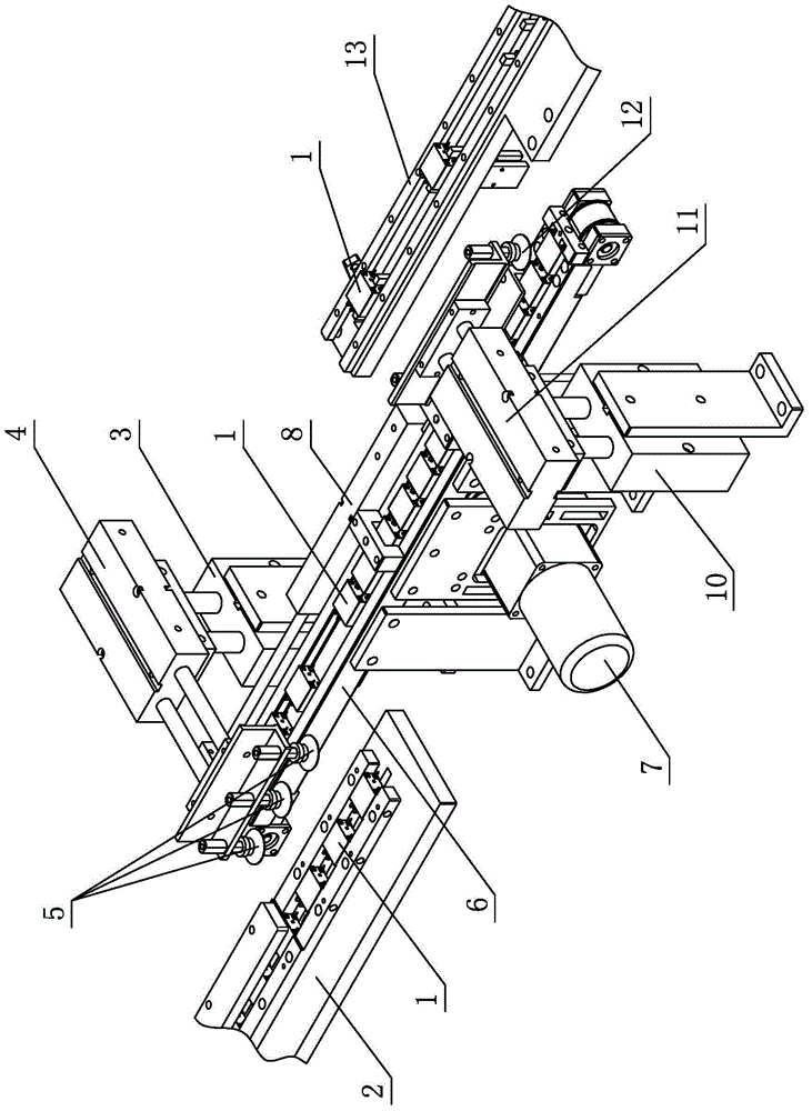
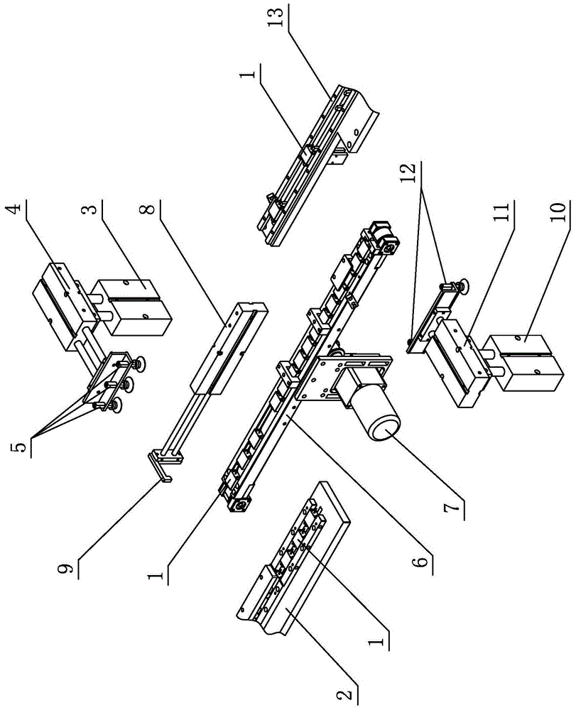
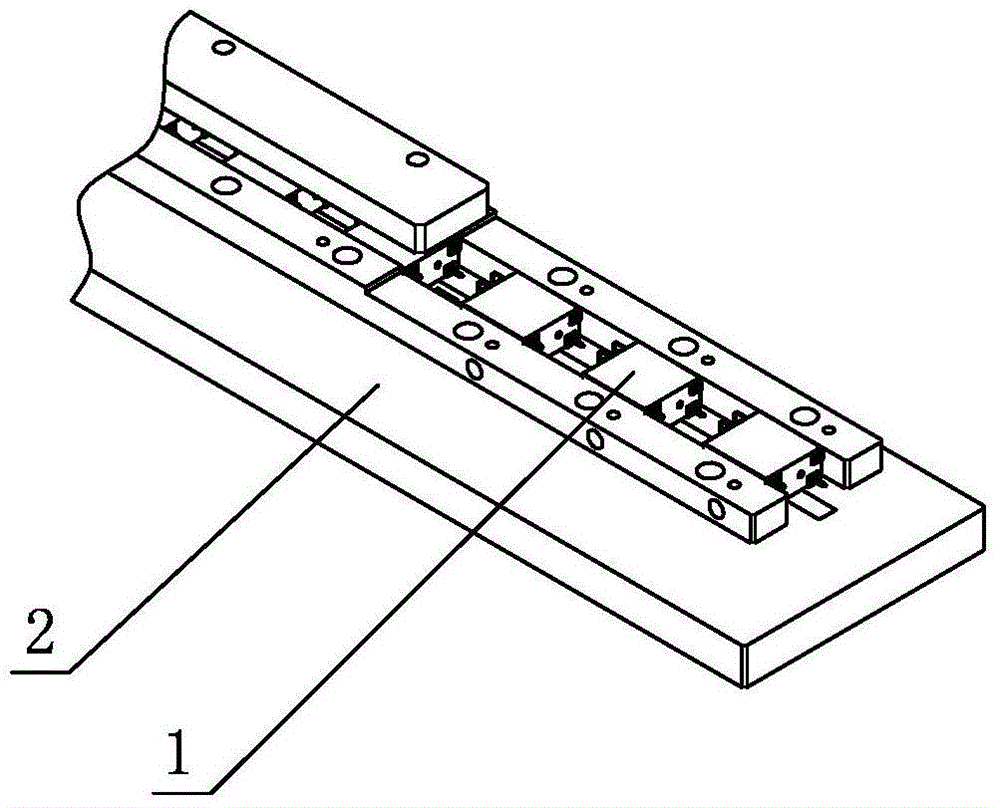
[0022] see Figure 1-Figure 8 , the vacuum sucker feeding equipment, including the feeding conveyor belt line 6 for conveying the product 1, the front and rear ends of the feeding conveyor belt line 6 are respectively provided with a discharge conveyor line 2 and a positioning conveyor line 13, the feed conveyor belt line 6 and the discharge conveyor line Between the conveying lines 2, between the feeding conveying belt line 6 and the positioning conveying line 13, a first vacuum sucker group 5 and a second vacuum sucker group 12 are arranged respectively; connected; when the equipment is started, the product 1 placed on the discharge conveyor line 2 is transported to the feeding conveyor belt line 6 by the first vacuum suction cup group 5, and then transported to the positioning conveyor line 13 by the second vacuum suction cup group 12, thereby Reali...


PUM


Abstract

Vacuum suction cup feeding equipment comprises a feeding conveyor belt line for conveying products. The front end of the feeding conveyor belt line and the rear end of the feeding conveyor belt line are provided with a discharge conveyor line and a positioning conveyor line respectively, a first vacuum suction cup group is arranged between the feeding conveyor belt line and the discharge conveyor line, and a second vacuum suction cup group is arranged between the feeding conveyor belt line and the positioning conveyor line; the first vacuum suction cup group and the second vacuum suction cup group are communicated with a connection tube and a vacuum generator respectively; when the equipment is started, the products placed on the discharge conveyor line are moved to the feeding conveyor belt line through the first vacuum suction cup group, and then are moved to the positioning conveyor line through the second vacuum suction cup group, so that automatic transformation and butt joint of the equipment are achieved. According to the vacuum suction cup feeding equipment, the cylinder piston motion material clamping mode is replaced by the vacuum suction cup method, vacuum cups communicated with the connection tube and the vacuum generator, when the equipment is started, gas is pumped out through the vacuum generator and the products are sucked firmly, so that the purpose of product moving is achieved, and practicability is high.

Description

technical field [0001] The invention relates to a feeding device, in particular to a vacuum sucker feeding device. Background technique [0002] Commonly used feeding devices are mainly based on cylinder clamping, cylinder pushing and linear vibration feeding. The product feeding process is completed through the thrust and pull of the piston rod in the cylinder and the positioning of the fixture. Due to the large volume of the cylinder and the fixture assembly, the large space occupied, and the complicated installation and maintenance, the manufacturing cost of this structure is high; if the linear vibration feeding structure is used, the product will be subjected to high-frequency vibration for a long time, and the internal mechanical structure of the product may be abnormal; Therefore, cylinder clamping, cylinder pushing and linear vibration feeding are not recommended for electronic component automation equipment such as relays. The feeding requirements for this type of ...

Claims


Application Information

Patent Timeline
Patent Type & Authority Patents(China)
IPC IPC(8): B65G47/91
Inventor 何家益林楚彬
Owner 广东格兰仕电器配件制造有限公司
Learn More