
A sealing ring cutting device

A cutting device and sealing ring technology, applied in metal processing and other directions, can solve problems such as lack of use and consumption of raw materials, and achieve the effect of avoiding waste and saving manpower

Active Publication Date: 2022-07-29
合肥恒盈橡塑科技有限公司
View PDF7 Cites 0 Cited by
  • Summary
  • Abstract
  • Description
  • Claims
  • Application Information

AI Technical Summary

Problems solved by technology

The above-mentioned patent has the following disadvantages: when cutting, a whole piece of rubber plate is used to cut the rubber sealing ring, and many parts are not used when cutting, which consumes more raw materials and cannot meet people's needs

Method used


Image

  • A sealing ring cutting device
  • A sealing ring cutting device
  • A sealing ring cutting device

Examples


Embodiment 1

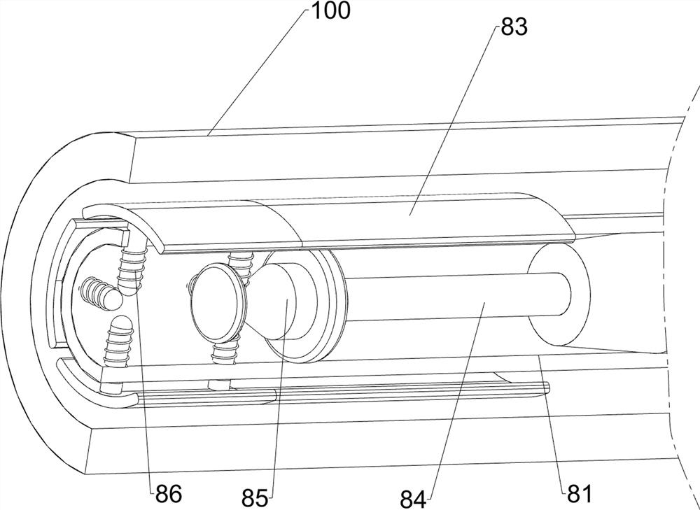
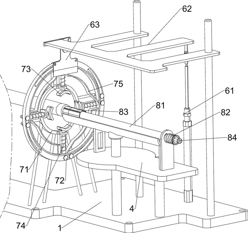
[0025] A sealing ring cutting device, such as Figure 1-3 As shown in the figure, it includes a base 1, a fixing rod 2, a connecting shaft 3, a connecting plate 4 and a placing plate 5. The top left side of the base 1 is connected with a fixing rod 2, and the right side of the top of the base 1 is rotatably connected with a connecting shaft 3 , the connecting shaft 3 is connected with a connecting plate 4, the top of the connecting shaft 3 is connected with a placing plate 5, and also includes a lifting and cutting assembly 6, a clamping assembly 7 and a pushing assembly 8, and the base 1 is provided with a lifting and cutting assembly 6 and The clamping component 7, the pushing component 8 is arranged between the placing plate 5 and the connecting plate 4.

[0026] The lifting and cutting assembly 6 includes an air cylinder 61, a sliding plate 62 and a cutting knife 63. A cylinder 61 is installed at the rear right side of the top of the base 1, a sliding plate 62 is slidably ...

Embodiment 2

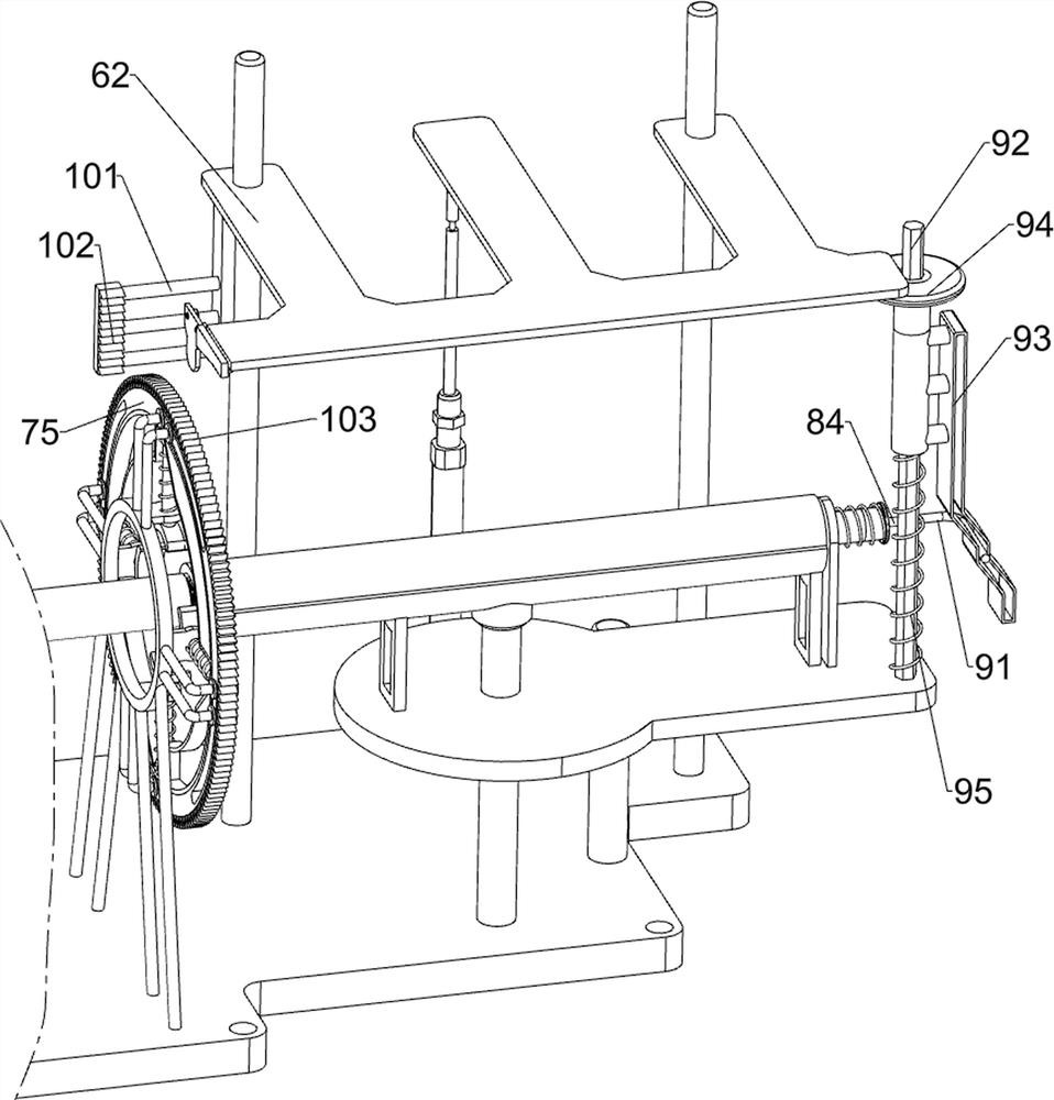
[0031] On the basis of Example 1, as Figure 4 As shown, it also includes a moving assembly 9. The moving assembly 9 includes an extension rod 91, a diamond rod 92, a guide frame 93, a connecting plate 94 and a second compression spring 95. The right side of the sliding rod 84 is connected with an extension rod 91. The connecting plate 4. A diamond-shaped rod 92 is connected to the right side of the top, and a guide frame 93 is slidably connected to the diamond-shaped rod 92. The guide frame 93 is slidingly matched with the extension rod 91. The top of the guide frame 93 is connected with a connecting plate 94. The connecting plate 94 is blocked by the bottom of the slide plate 62 , a second compression spring 95 is connected between the guide frame 93 and the connecting plate 4 .

[0032]Initially, the telescopic rod of the air cylinder 61 is in a slightly extended state, the return spring 82 is in a compressed state, and the second compression spring 95 is in a compressed st...


PUM


Abstract

The invention relates to a cutting device, in particular to a sealing ring cutting device. The technical problem to be solved by the present invention is how to design a sealing ring cutting device that does not waste raw materials during operation. In order to solve the above technical problems, the present invention provides such a sealing ring cutting device, which includes: a base, a fixing rod is connected to one side of the top of the base; A connecting plate is connected; a placing plate is connected to the top of the connecting shaft; a lifting and cutting component is arranged on the base; a clamping component is arranged on the base; a pushing component is arranged between the placing plate and the connecting plate between. The invention cuts the rubber sealing ring through the coordinated operation of the lifting and cutting component, the clamping component and the pushing component, so as to achieve the effect of making the rubber sealing ring.

Description

technical field [0001] The invention relates to a cutting device, in particular to a sealing ring cutting device. Background technique [0002] With the continuous development of modern society, water pipes are installed in most houses in modern society, and equipment such as faucets or showers are installed at the outlet of the water pipes. When installing equipment such as faucets or showers, it is necessary to connect the installation place The rubber sealing ring can seal the water on the faucet or the connection between the shower and the water pipe, so as to avoid the water flowing out and causing waste. [0003] After searching, the authorized patent publication number is CN207105042U, which discloses a sealing ring cutting machine, which has a simple structure and can quickly realize high-precision cutting of rubber sealing rings. The cutting knife uses the positioning knife as the center of the circle to cut the raw material of the sealing ring, thereby realizing t...

Claims


Application Information

Patent Timeline
Patent Type & Authority Patents(China)
IPC IPC(8): B26D1/08B26D7/02B26D7/06
CPCB26D1/08B26D7/02B26D7/06
Inventor 杨宇斌
Owner 合肥恒盈橡塑科技有限公司
Learn More