
Pull-up device for spinning bobbin

A bobbin and textile technology, which is applied in the field of pulling devices for textile bobbins, can solve the problems of reducing work efficiency and difficult to pull out the bobbins.

Inactive Publication Date: 2014-07-23
HUNAN JICHANG SILK
View PDF11 Cites 3 Cited by
  • Summary
  • Abstract
  • Description
  • Claims
  • Application Information

AI Technical Summary

Problems solved by technology

In the process of bobbin winding yarn, in order to prevent the bobbin from loosening, people often insert the bobbin tightly on the spindle of the textile machine. After the yarn winding is completed, the bobbin is difficult to pull out, seriously reducing work efficiency

Method used


Image

  • Pull-up device for spinning bobbin
  • Pull-up device for spinning bobbin
  • Pull-up device for spinning bobbin

Examples


Embodiment 1

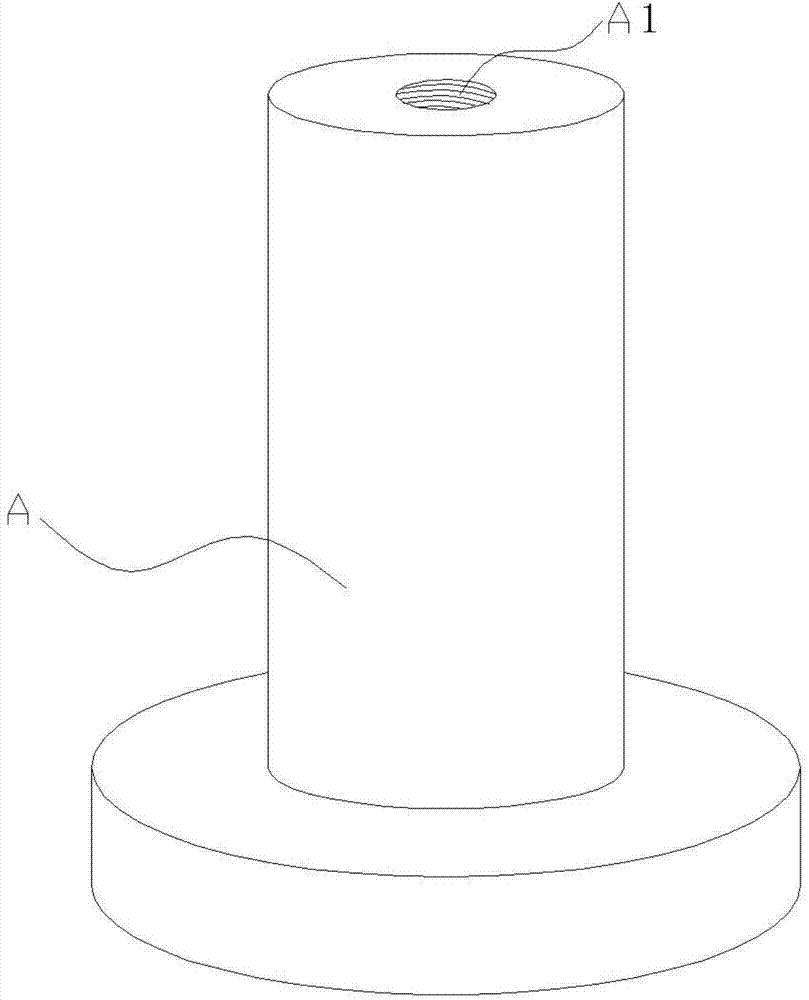
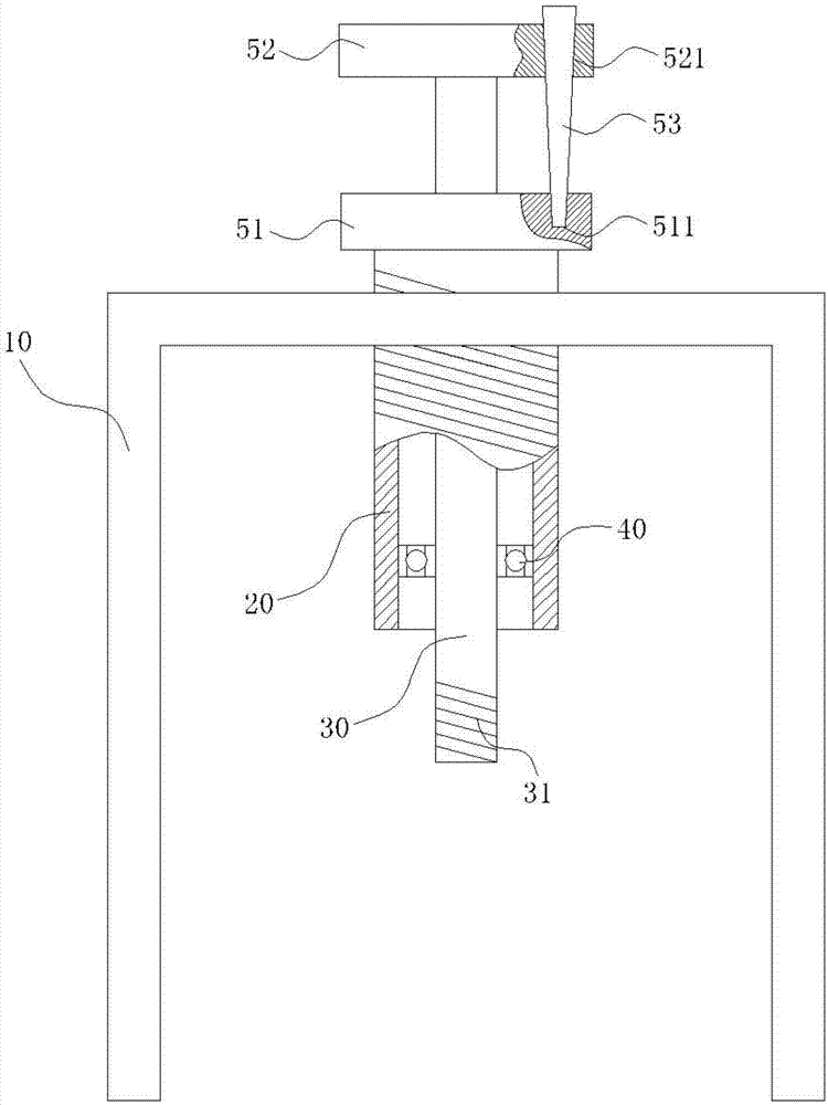
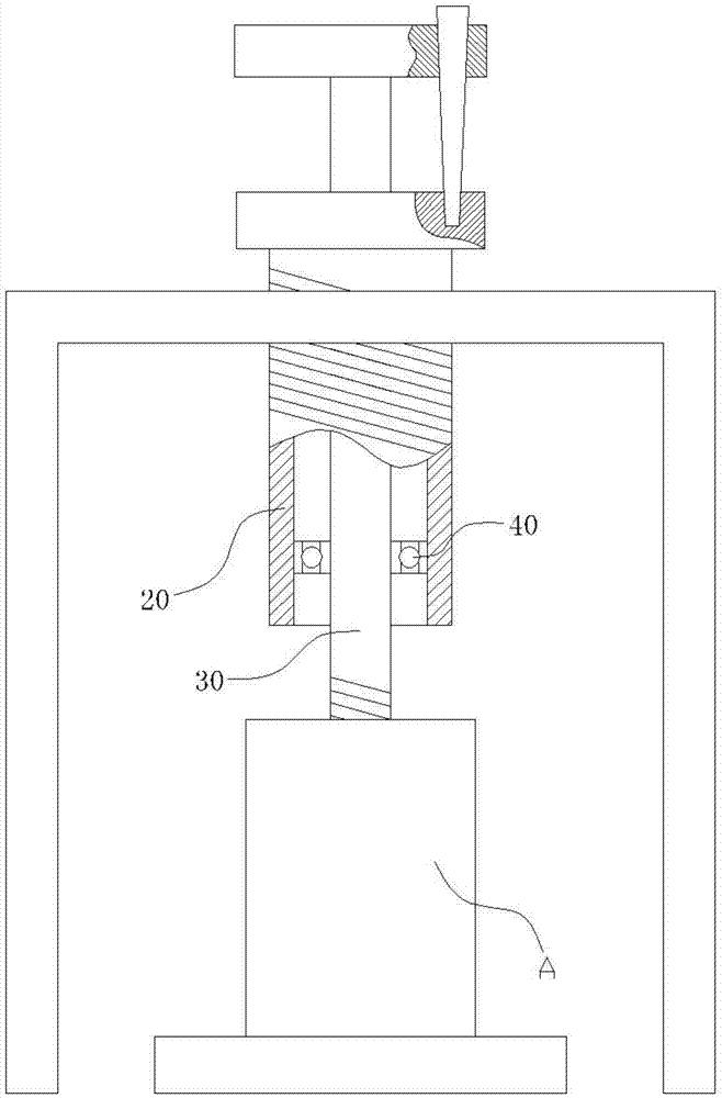
[0027] Such as Figure 1~3 As shown, a pull-up device for a textile bobbin includes a bracket 10 that can cover the bobbin A, a spiral tube 20 threaded with the bracket 10, a screw rod 30 installed in the spiral tube 20, the spiral tube 20 and The screw rods 30 are connected together by a bearing 40, and one end of the screw rod 30 is provided with a screw thread 31 matched with the screw hole A1 on the top of the bobbin tube A, and the screw thread 31 has the same rotation direction as that on the spiral tube 20, One end of the screw rod 30 protrudes from the spiral tube 20 for a certain distance, and the other end of the screw rod 30 is installed with a locking device for locking and disassembling the screw rod 30 and the spiral tube 20 . Wherein, the direction of rotation of the thread 31 is left-handed or right-handed.

[0028] The locking device includes a fixed block 51 installed on the end of the spiral tube 20, a fixed block 52 installed on the end of the screw rod 30...

Embodiment 2

[0030] Such as figure 1 , 4 As shown in ~7, a pull-up device for a textile bobbin includes a bracket 10 that can cover the bobbin A, a spiral tube 20 threaded with the bracket 10, and a screw rod 30 installed in the spiral tube 20. The spiral tube 20 and the screw rod 30 are connected together through a bearing 40. One end of the screw rod 30 is provided with a screw thread 31 matched with the screw hole A1 on the top of the bobbin tube A. Similarly, one end of the screw rod 30 extends out of the spiral tube 20 for a certain distance, and the other end of the screw rod 30 is installed with a locking device for locking and disassembling the screw rod 30 and the spiral tube 20 . Wherein, the direction of rotation of the thread 31 is left-handed or right-handed.

[0031] The locking device includes a movable block 54 with a square through hole 541 in the central position, and a fixed block 55 installed at the end of the spiral tube 20. The movable block 54 is provided with a pr...


PUM


Abstract

The invention discloses a pull-up device for a spinning bobbin. The pull-up device comprises a support, a spiral pipe in threaded connection with the support and a spiral rod installed in the spiral pipe, wherein the spiral pipe is connected with the spiral rod through a bearing, one end of the spiral rod is provided with threads and stretches out of the spiral pipe by a certain distance, and a locking device is arranged at the other end of the spiral rod and used for locking the spiral rod and the spiral pipe together or separating the spiral rod from the spiral pipe. The spiral rod and the spiral pipe are locked together by the locking device, and the end of the descending spiral rod is screwed into a screw hole in the top of the bobbin; the spiral rod and the spiral pipe are separated from each other by the locking device, and the spiral pipe is screwed and ascends; under the action of the bearing, the spiral rod drives the spiral pipe to ascend. By means of the pull-up device, the bobbin can be conveniently pulled up, the labor intensity of operators is lowered, and the working efficiency is improved.

Description

Technical field: [0001] The invention relates to the field of textile machinery design, in particular to a pulling device for a textile bobbin. Background technique [0002] In textile production, people usually wind the yarn with the bobbin, and after the yarn winding is completed, it is taken off together with the bobbin and used for the next process. In the process of bobbin winding yarn, in order to prevent the bobbin from loosening, people often insert the bobbin tightly on the spindle of the textile machine. After the yarn winding is completed, the bobbin is difficult to pull out, seriously reducing work efficiency. Contents of the invention [0003] The technical problem to be solved by the present invention is to provide a pulling device for textile machinery, which can conveniently pull out bobbins of textile machinery. [0004] The invention provides the following technical solutions: a pulling device for textile bobbins, including a bracket that can cover the ...

Claims


Application Information

Patent Timeline
IPC IPC(8): B65H67/04
Inventor 叶芳
Owner HUNAN JICHANG SILK
Learn More