Unmanned aerial vehicle for detecting power cable faults
A technology of power cables and drones, applied in the field of drones, can solve the problems of low inspection efficiency and achieve the effects of improving inspection efficiency, detection efficiency, and battery life
- Summary
- Abstract
- Description
- Claims
- Application Information
AI Technical Summary
Problems solved by technology
Method used
Image
Examples
Embodiment 1
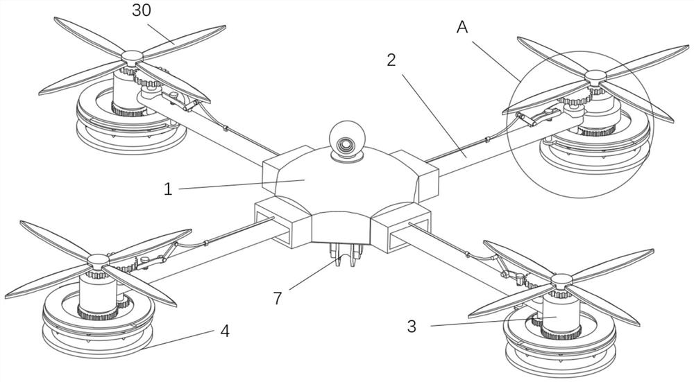
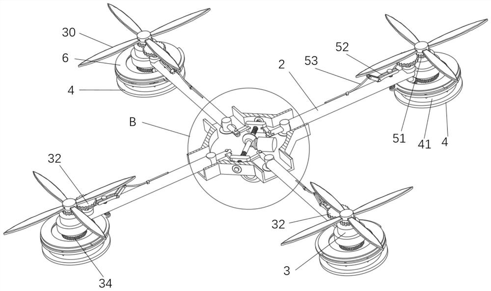
[0034]Such asFigures 1 to 10 As shown, the present invention provides a drone that detects the fault of the power cable, including the body 1, the arm 2, and a drive motor 3 with paddle 30, the arm 2 is four, four machine arm 2 The symmetrical hinges are hinged to the body 1, and the drive motor 3 is provided at the end of the arm 2, the drive motor 3 can be positive inversion; the body 1 is provided with a exhibition device, and the exhibition device is connected to the end of the arm 2 to pass through The exhibition device controls four arm 2 together to perform the exhibition movement, thereby adjusting the deployment width of the arm 2; the lower end of the drive motor 3 can be rotated with a roller 4, and the roller 4 is passed through the transmission assembly and the drive motor 3 output. The drive is connected so that the drive motor 3 is rotated by the transmission assembly to rotate to travel on the high voltage cable; the roller 4 is provided with a roller groove 41 in th...
Embodiment 2
[0042]Such asFigure 5 ,Figure 7 And andFigure 9 As shown in connection with the technical solution of Example 1, in the present embodiment, the pulley 53 assembly includes a tab rod 51, a V-shaped member 52, a pulley 53, a tie rod 54, and a ring semi-circular plate 55, and the tab 51 can be driven by the drive motor 56. The rotation is provided in the body 1, and the V-shaped member 52 is hinged on the arm 2, and the annular semi-circular plate 55 is provided between the annular restricted member 6, and the ring restricted member 6 is connected to one end of the V-shaped member 52 by the lever 54, v. The other end of the sheet 52 is connected to the tab 51 by the pull line 53 to rotate one end of the V-shaped member 52 by the pull line 53, so that the other end of the V-shaped member 52 is rotated to drive the tie rod 54 to rise. Where the V-shaped member 52 is two plate structures, one end is an opening structure, and the tie rod 54 is opened in the V-shaped member 52 via a limit p...
Embodiment 3
[0047]Such asFigure 1 to 8As shown in connection with the technical solution of Example 2, in the present embodiment, the cross section of the roller groove 41 is a U-shaped structure, and the roller groove 41 of the U-shaped structure can increase the contact area of the roller 4 and the high voltage cable, thereby reducing high pressure. The impact of the cable swaying on the roller 4, thereby reducing the problem that the drone causes detachment caused by high voltage cable shaking.
[0048]By providing the elastic limit piece 5 in the roller 4 in the roller 4, the roller 4 can be limited to the roller 4 by the elastic limit member 5 during the rotation of the roller 4 to rotate on the high voltage cable. The cable is caused by the problem of the wind swing causes the roller 4 to disengage the high voltage cable; the roller 4 drives the elastic limit piece 5 and the high voltage cable in the process, so that the elastic limit piece 5 follows the roller 4 to move to high pressure O...
PUM
 Abstract
Description
Claims
Application Information
 - R&D
- Intellectual Property
- Life Sciences
- Materials
- Tech Scout
- Unparalleled Data Quality
- Higher Quality Content
- 60% Fewer Hallucinations
Browse by: Latest US Patents, China's latest patents, Technical Efficacy Thesaurus, Application Domain, Technology Topic, Popular Technical Reports.
© 2025 PatSnap. All rights reserved.Legal|Privacy policy|Modern Slavery Act Transparency Statement|Sitemap|About US| Contact US: help@patsnap.com


