
Rotating mechanism of gate seat type crane

A portal crane and slewing mechanism technology, applied in cranes and other directions, can solve the problems of increasing friction, reducing the working stability of moving parts, shortening the service life of parts, etc., to achieve the effect of improving work efficiency, avoiding unilateral wear, and moving smoothly

Inactive Publication Date: 2014-07-23
安徽金斗机械制造有限责任公司
View PDF6 Cites 8 Cited by
  • Summary
  • Abstract
  • Description
  • Claims
  • Application Information

AI Technical Summary

Problems solved by technology

[0002] At present, the slewing mechanisms of medium and small gantry cranes produced in China all use a transmission gear, which is installed on one side of the large ring gear of the slewing ring, so that both the transmission gear and the inner ring of the slewing ring bear a large radial force. Increase the friction between components, shorten the service life of parts, and seriously reduce the working stability of moving parts

Method used


Image

  • Rotating mechanism of gate seat type crane
  • Rotating mechanism of gate seat type crane
  • Rotating mechanism of gate seat type crane

Examples


Embodiment Construction

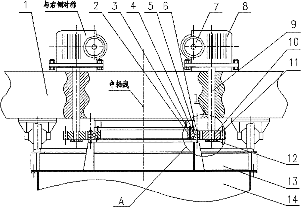
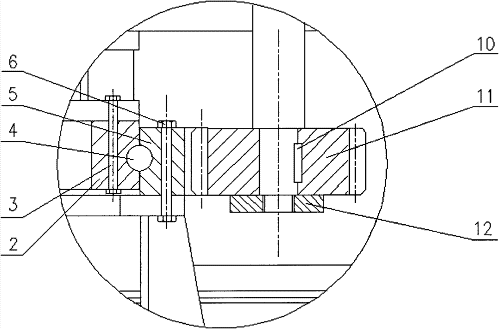
[0021] exist figure 1 Among them, the motor 7 drives the reducer 8, the transmission gear shaft 9 and the transmission gear 11 fixed on the transmission gear shaft 9 through the flat key 10 and the lock nut 12 to rotate, and the slewing ring meshing with the transmission gear 11 passes through the outer ring Fastening screw 6 is fixed on the circular chassis 13 that links to each other with base 14, can't rotate, so transmission gear 11 both has self-rotation, must do circular motion again around slewing ring ring gear. At the same time, the base of the reducer 8 is welded on the slewing platform 1, and the inner ring 2 of the slewing bearing is connected to the bottom of the slewing platform 1 through the inner ring fastening bolt 3, so all parts connected to the slewing platform 1 are rotated around Support the circular motion of the large ring gear 5. At the same time, a steel ball 4 is installed between the large ring gear 5 of the slewing ring and the inner ring 2 of the...


PUM


Abstract

The invention discloses a rotating mechanism of a gate seat type crane. A rotating platform (1) is fixedly connected with a rotary support inner ring (2); the rotary support inner ring (2) is connected with a rotary support large tooth ring (5) in a rolling manner through a steel ball (4) and can rotate in the rotary support large tooth ring (5); the rotary support large tooth ring (5) is fixedly connected with a circular base plate (13) through a fastening bolt (6); two same transmission gears (11) are symmetrically distributed on two sides of the rotary support large tooth ring and are meshed with the rotary support large tooth ring; a motor (7) is connected with the transmission gears (11) through a speed reducer (8) and a transmission gear shaft (9) and drives the transmission gears (11) to rotate; the transmission gears (11) enable the rotating platform (1) to rotate under the action of counterforce. Resultant force of radial force on the rotating support inner ring is zero, so that single-edge abrasion between the rotary support large tooth ring and the steel ball is avoided.

Description

technical field [0001] The invention relates to a slewing mechanism of a portal crane. Background technique [0002] At present, the slewing mechanisms of medium and small gantry cranes produced in China all use a transmission gear, which is installed on one side of the large ring gear of the slewing ring, so that both the transmission gear and the inner ring of the slewing ring bear a large radial force. It increases the friction between the components, shortens the service life of the parts, and seriously reduces the working stability of the moving parts. Contents of the invention [0003] The technical problem to be solved by the present invention is to provide a slewing mechanism of a portal crane. The mechanism is simple and easy to operate, reduces the friction between the parts, prolongs the service life, and improves the smoothness of the moving parts. [0004] In order to solve the above technical problems, the technical solution adopted by the present invention...

Claims


Application Information

Patent Timeline
IPC IPC(8): B66C23/84
Inventor 程明根宋志良
Owner 安徽金斗机械制造有限责任公司
Learn More