Spindle blade of textile machine spindle

A spindle and spindle rod technology, which is applied in the direction of textiles and papermaking, can solve the problems that affect the twist of the yarn and cannot be matched

Inactive Publication Date: 2014-07-23
重庆恒进源茧丝绸有限公司
View PDF6 Cites 6 Cited by
  • Summary
  • Abstract
  • Description
  • Claims
  • Application Information

AI Technical Summary

Problems solved by technology

[0005] However, in actual operation engineering, due to the different forces on the elastic elements on the spindle bar and the different elastic coefficients of the elastic elements, although the elastic elements can clamp the bobbin, they cannot make the center of the bobbin The axis basically coincides with the central axis of the spindle bar, and then there are quality problems such as affecting the twist of the yarn

Method used


Image

  • Spindle blade of textile machine spindle
  • Spindle blade of textile machine spindle
  • Spindle blade of textile machine spindle

Examples


Embodiment Construction

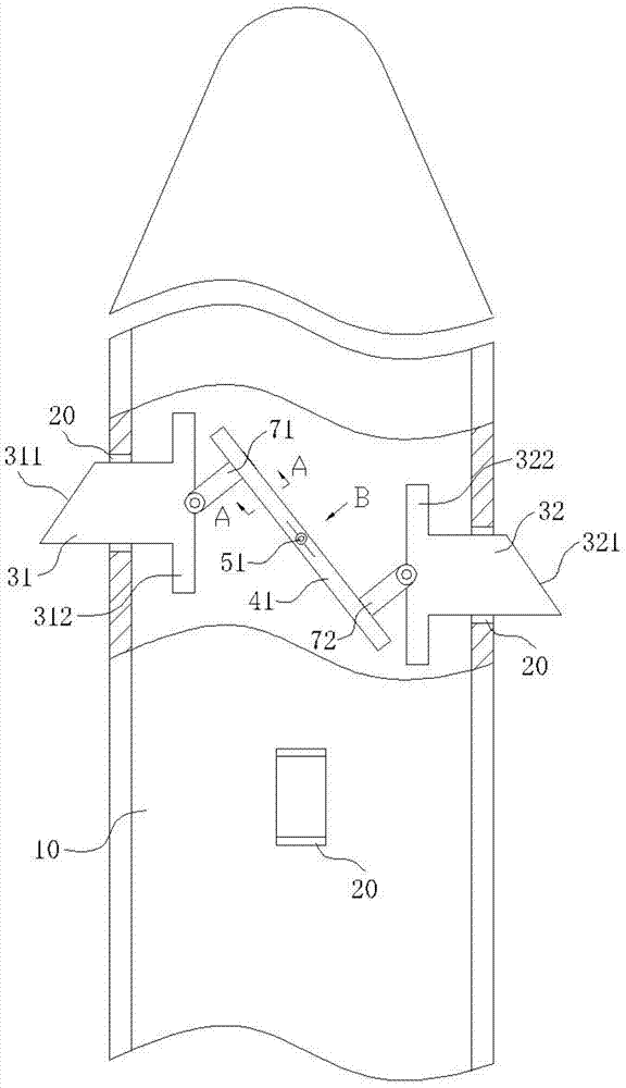
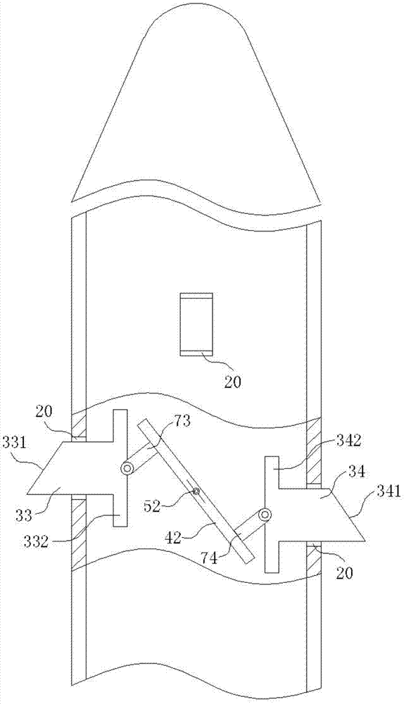
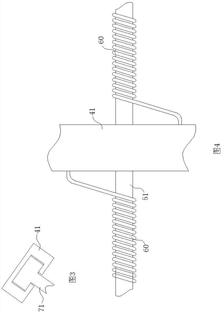
[0024] like Figure 1~4 As shown, a spindle rod of a spinning machine spindle includes a hollow rod body 10, four openings 20 provided on the rod body 10, a telescopic block 31, a telescopic block 32, a telescopic block 33, and a telescopic block that can expand and contract in the opening 20. Block 34, the four openings 20 are evenly distributed along the circumference of the rod body 10, the telescopic block 31, the telescopic block 32, the telescopic block 33, and the telescopic block 34 are located on the outer part of the rod body and are provided with inclined surfaces 311, 321, and 331. The slope 341, the telescopic block 31, the telescopic block 32, the telescopic block 33, and the telescopic block 34 are located inside the rod body 10 and are provided with a protruding part 312, a protruding part 322, a protruding part 332 and a protruding part 342. It also includes a lever 41 and a lever 42. The telescopic block 31 and the telescopic block 32 are movably connected to...


PUM


Abstract

The invention discloses a spindle blade of a textile machine spindle. The spindle blade of the textile machine spindle comprises a hollow rod body (10). The rod body (10) is provided with four openings (20) and telescopic blocks which can be stretched out and drawn back in the openings (20). The spindle blade of the textile machine spindle further comprises a lever, the telescopic blocks are connected at the two ends of the lever in a movable mode, the lever (41) is arranged on a cross lever (51), the cross lever penetrates through the middle point of the lever, a cylindrical spring (60) is arranged between the cross lever and the lever, and the cross lever penetrates through the axial line of the rod body (10). When a bobbin is arranged on the spindle blade in a sleeved mode from top to bottom, the lower end of the bobbin makes contact with the inclined faces of the telescopic blocks, the telescopic blocks retract towards the inner side of the rod body, the telescopic blocks drive the lever to rotate around the cross lever, the lever drives the other end of each telescopic block to retract towards the inner side of the rod body. Due to the fact that the cross lever penetrates through the middle point of the lever, the cross lever penetrates through the axial line of the rod body, and the retracting distances towards the inner side of the rod body of the two telescopic blocks are the same. By means of the technical scheme, the center positioning effect of the bobbin is achieved.

Description

technical field [0001] The invention relates to the field of textile machinery design, in particular to a spindle bar of a textile machinery spindle. Background technique [0002] The spindle is an important part of the twisting and winding machinery in the textile machine, and is widely used in textile machinery such as wool spinning frames, twisting frames and worsted spinning frames; the bobbin is the spinning container used for the supporting operation of the spindle. The technical performance and running quality of spindles and bobbins are closely related to yarn quality, power consumption, environmental noise and labor productivity. [0003] Spindle of spinning machine is mainly composed of spindle rod, spindle plate, spindle bladder and spindle foot, etc. The spindle plate fixed on the spindle rod is the driving part of the spindle, and the spindle foot is the supporting seat of the spindle. The spindle rod rotates at high speed with the spindle as the bearing. The ...

Claims


Application Information

Patent Timeline
Patent Type & Authority Applications(China)
IPC IPC(8): D01H7/16
Inventor 徐增群
Owner 重庆恒进源茧丝绸有限公司
Why Eureka
Try Eureka