
Rotary rapid eyeglass leg replacement structure

A mirror foot and mirror frame technology, which is applied in the field of rotating and quick-changing mirror foot structures, can solve problems such as inconvenient operation, achieve the effects of easy disassembly and carrying, satisfying mirror foot matching, and easy manufacturing

Inactive Publication Date: 2014-07-23
XIAMEN KISSEYEWEAR IND
View PDF10 Cites 0 Cited by
  • Summary
  • Abstract
  • Description
  • Claims
  • Application Information

AI Technical Summary

Problems solved by technology

However, the existing mirror feet need to use special tools when replacing them, so that the mirror feet can be smoothly removed from the mirror frame for replacement, and the operation is very inconvenient

Method used


Image

  • Rotary rapid eyeglass leg replacement structure
  • Rotary rapid eyeglass leg replacement structure
  • Rotary rapid eyeglass leg replacement structure

Examples


Embodiment Construction

[0017] The present invention will be further described below in conjunction with accompanying drawing:

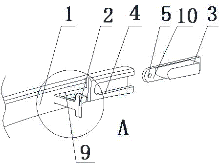
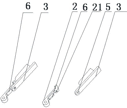
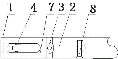
[0018] Such as figure 1 , figure 2 , image 3 and Figure 4 As shown, the present invention includes a mirror frame with a frame foot connection 3 and a mirror foot 1 matched with the frame foot connection 3, a "T" shaped pressure block 2 is arranged on the mirror foot 1, and a A groove 9 is provided to cooperate with the "T"-shaped pressure block, and the groove 9 is provided with a sliding groove 4 near the connection of the frame foot connection 3, and the frame foot connection 3 is arranged in the sliding groove 4, the "T"-shaped pressing block 2 is provided with a positioning post 21, and the frame foot connection 3 is provided with a positioning connection hole 5 that cooperates with the positioning post 21.

[0019] Such as figure 1 As shown, the "T"-shaped pressing block 2 is provided with a positioning protrusion 6, and the groove 9 is provided with a positio...


PUM


Abstract

The invention discloses a rotary rapid eyeglass leg replacement structure which comprises an eyeglass frame provided with a frame leg connector and eyeglass legs matched with the frame leg connector, wherein T-shaped pressing blocks are arranged on the eyeglass legs; grooves matched with the T-shaped pressing blocks are formed in the eyeglass legs; a chute is formed in the joint, which is close to the frame leg connector, of the grooves; the frame leg connector is arranged in the chute; positioning columns are arranged on the T-shaped pressing blocks; positioning connecting holes matched with the positioning columns are formed in the frame leg connector. The T-shaped pressing blocks arranged on the eyeglass legs are fixedly connected with the frame leg connector and the eyeglass legs, so that detachment and carrying are convenient; the rotary rapid eyeglass leg replacement structure is simple in structure and easy to manufacture, and the eyeglass leg matching requirements of customers on types are met.

Description

technical field [0001] The invention relates to a mirror leg structure, in particular to a rotating and quickly changing mirror leg structure. Background technique [0002] At present, the processing of the mirror feet of sunglasses or glasses is mainly connected by forming injection hinges or metal hinges. The mirror feet are generally pivoted to the frame by screw locking, so that the mirror feet can rotate 90 degrees around the screws. However, in modern life, in addition to the function of supporting the mirror frame, the temples also begin to take on some additional functions: for example, young people who are chasing fashion can obtain a sense of fashion by changing the temples; people who love sports are running and jumping. , Even extreme sports need to use temples with better fixing performance (such as binding with elastic bands) to prevent the glasses from falling off and affecting personal safety. However, it is very inconvenient to operate the existing mirror f...

Claims


Application Information

Patent Timeline
Patent Type & Authority Applications(China)
IPC IPC(8): G02C5/14
Inventor 高光辉
Owner XIAMEN KISSEYEWEAR IND
Learn More